
Page 181 - Gas Purification 5E
P. 181
168 Gas Purijkation
the flooding velocity given by Crawford and Wilke, as flooding in LE treaters can occur at
209 of the flooding velocity predicted by that correlation.
Distributors and Dispersers. If amine is the continuous phase, LPG must be evenly dis-
persed at the bottom of each additional bed of random packing. Usually this is accomplished
with a ladder type LPG distributor beneath the bottom bed and a separate disperserlsupport
plate. beneath each additional bed of packing. The LPG ladder distributor holes should be
pointed in the upward direction to minimize LPG entrainment in the rich amine use and
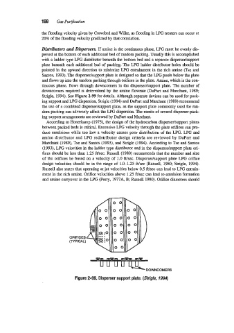
Santos, 1993). The disperser/support plate is designed so that the LPG pools below the plate
and flows up into the random packing through orifices in the plate. Amine, which is the con-
tinuous phase, flows through downcomers in the disperser/support plate. The number of
downcomers required is determined by the amine flowrate (DuPart and Marchant, 1989;
Strigle, 1994). See Figure 2-99 for details. Although separate devices can be used for pack-
ing support and LPG dispersion, Strigle (1994) and DUPart and Marchant (1989) recommend
the use of a combined dispersedsupport plate, as the support plate commonly used for ran-
dom packing can adversely affect the LPG dispersion. The merits of several disperser-pack-
ing support arrangements are reviewed by DuPart and Marchant.
According to Honerkamp (1973, the design of the hydrocarbon dispersdsupport plates
between packed beds is critical. Excessive LPG velocity through the plate dices can pro-
duce emulsions while too low a velocity causes poor distribution of the LPG. LPG and
amine distributor and LPG redistributor design criteria are reviewed by DuPart and
Marchant (1989), Tse and Santos (1993), and Strigle (1994). According to Tse and Santos
(1993), LPG velocities in the ladder type distributor and in the dispersedsupport plate on-
fices should be less than 1.25 ft/sec. Russell (1980) recommends that the number and size
of the orifices be based on a velocity of 1.0 ft/sec. Disperser/support plate LPG orifice
design velocities should be in the range of 1.G1.25 Wsec (Russell, 1980; Strigle, 1994).
Russell also states that operating at jet velocities below 0.5 Wsec can lead to LPG entrain-
ment in the rich amine. Orifice velocities above 1.25 Wsec can lead to emulsion formation
and amine carryover in the LPG (Perry, 1977A, B; Russell 1980). Orifice diameters should
ORIFICES
(TYPICAL)
DOWNCOMERS
Figure 2-99. Disperser support plate. (Sfrigle, 7994)