
Page 67 - Gas Purification 5E
P. 67
dlkanolamines for Hvdrogem Sulfide and Carbon Dioxide Removal 57
,600
\
\
'.
- 500
0.301
I
I
( 1 45 50 55 60 65
Wt%DGA
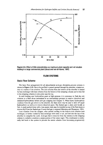
Figure 2-9, Effect of DGA concentration on maximum plant capacity and net solution
loading in a large commercial plant (Huval and van de Venne, 7980
FLOW SYSTEMS
Basic Flow Scheme
The basic flow arrangement for all alkanolamhe acid-gas absorption-process systems is
shown in Figure 2-10. Gas to be purified is passed upward through the absorber, countercur-
rent m a stream of the solution. The rich solution hm the bottom of the absorber is heated
by heat exchange with lean solution from the bottom of the stripping column and is then fed
to the stripping column at some point near the top.
In units treating sour hydrocarbon gases at high pressure, it is customary to flash the rich
solution in a flash drum maintained at an intermediate pressure to remove dissolved and
entrained hydrocarbons before acid gas stripping (see Chapter 3). When heavy hydrocarbons
condense from the gas stream in the the flash drum may be used to skim off liquid
hydrocarbons as well as to remove dissolved gases. The flashed gas is often used locally as
fuel. A small packed tower with a lean amine wash may be installed on top of the flash drum to
remove H2S from the flashed gas if sweet fuel gas is required (Manning and Thompson, 1991).
Lean solution from the stripper, after partial cooling in the lean-to-rich solution heat
exchanger, is further cooled by heat exchange with wafer or air, and fed into the top of the
absorber to complete the cycle. Acid gas that is removed from the solution in the stripping
column is cooled to condense a major portion of the water vapor. This condensate is contin-
ually fed back to the system to prevent the amine solution from becoming progressively