
Page 68 - Gas Purification 5E
P. 68
58 Gas Purgcation
PURIFIED SOLUTION = 1 1-
,ETHANOLAMINE
GAS STEAM
ACID GAS
TO DISPOSAL
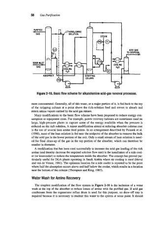
Figure 2-10. Basic flow scheme for alkanolamine acid-gas removal processes.
more concentrated. Generally, all of this water, or a major portion of it, is fed back to the top
of the stripping column at a point above the rich-solution feed and serves to absorb and
return amine vapors carried by the acid gas stream.
Many modifications to the basic flow scheme have been proposed to reduce energy con-
sumption or equipment costs. For example, power recovery turbines are sometimes used on
large, high-pressure plants to capture some of the energy available when the pressure is
reduced on the rich solution. A minor modification aimed at reducing absorber column cost
is the use of several lean amine feed points. In an arrangement described by Polasek et al.
(1990), most of the lean solution is fed near the midpoint of the absorber to remove the bulk
of the acid gas in the lower portion of the unit. Only a small stream of lean solution is need-
ed for final clean-up of the gas in the top portion of the absorber, which can therefore be
smaller in diameter.
A modification that has been used successfully to increase the acid gas loading of the rich
amine (and thereby decrease the required solution flow rate) is the installation of a side cool-
er (or intercooler) to reduce the temperature inside the absorber. The concept has proved par-
ticularly useful for DGA plants operating in Saudi Arabia where air cooling is used (Huval
and van de Venne, 1981). The optimum location for a side cooler is reported to be the point
where half the absorption occurs above and half below the cooler, which results in a location
near the bottom of the column (Thompson and King, 1987).
Water Wash for Amine Recovery
The simplest modification of the flow system in Figure 2-10 is the inclusion of a water
wash at the top of the absorber to reduce losses of amine with the purified gas. If acid gas
condensate from the regenerator reflux drum is used for this purpose, no draw-off tray is
required because it is necessary to readmit this water to the system at some point. It should