
Page 170 - Geothermal Energy Renewable Energy and The Environment
P. 170
156 Geothermal Energy: Renewable Energy and the Environment
10,000.0
0°C
1000.0
350°C
400°C
100.0 Liquid 250°C 1
300°C
Pressure (bars) 10.0 150°C
200°C
1.0 100°C Vapor
4 20% 40% 60%
0.1 50°C 2 2 * 3
Liquid + Vapor 80%
25°C
0.01
0 500 1000 1500 2000 2500 3000 3500
Enthalpy (kJ/kg)
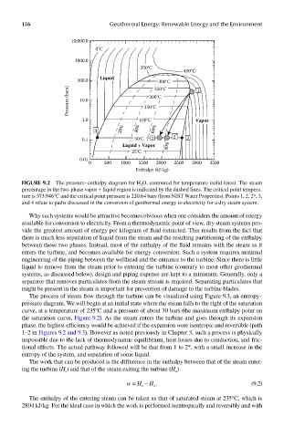
FIGUre 9.2 The pressure–enthalpy diagram for H 2 O, contoured for temperature (solid lines). The steam
percentage in the two-phase vapor + liquid region is indicated by the dashed lines. The critical point tempera-
ture is 373.946°C and the critical point pressure is 220.64 bars (from NIST Water Properties). Points 1, 2, 2*, 3,
and 4 relate to paths discussed in the conversion of geothermal energy to electricity for a dry steam system.
Why such systems would be attractive becomes obvious when one considers the amount of energy
available for conversion to electricity. From a thermodynamic point of view, dry steam systems pro-
vide the greatest amount of energy per kilogram of fluid extracted. This results from the fact that
there is much less separation of liquid from the steam and the resulting partitioning of the enthalpy
between those two phases. Instead, most of the enthalpy of the fluid remains with the steam as it
enters the turbine, and becomes available for energy conversion. Such a system requires minimal
engineering of the piping between the wellhead and the entrance to the turbine. Since there is little
liquid to remove from the steam prior to entering the turbine (contrary to most other geothermal
systems, as discussed below), design and piping expense are kept to a minimum. Generally, only a
separator that removes particulates from the steam stream is required. Separating particulates that
might be present in the steam is important for prevention of damage to the turbine blades.
The process of steam flow through the turbine can be visualized using Figure 9.3, an entropy–
pressure diagram. We will begin at an initial state where the steam falls to the right of the saturation
curve, at a temperature of 235°C and a pressure of about 30 bars (the maximum enthalpy point on
the saturation curve, Figure 9.2). As the steam enters the turbine and goes through its expansion
phase, the highest efficiency would be achieved if the expansion were isentropic and reversible (path
1–2 in Figures 9.2 and 9.3). However as noted previously in Chapter 3, such a process is physically
impossible due to the lack of thermodynamic equilibrium, heat losses due to conduction, and fric-
tional effects. The actual pathway followed will be that from 1 to 2*, with a small increase in the
entropy of the system, and separation of some liquid.
The work that can be produced is the difference in the enthalpy between that of the steam enter-
ing the turbine (H ) and that of the steam exiting the turbine (H )
x
e
w = H – H . (9.2)
x
e
The enthalpy of the entering steam can be taken as that of saturated steam at 235°C, which is
2804 kJ/kg. For the ideal case in which the work is performed isentropically and reversibly and with