
Page 288 - Geothermal Energy Systems Exploration, Development, and Utilization
P. 288
264 5 Geothermal Reservoir Simulation
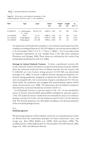
Table 5.2 Dimensions and hydraulic properties of the
artificial hydraulic fractures under in situ conditions.
Well Type Layer Depth Height Length K f
−1
(m) (m) (m) (m s )
EGrSk3/90 2 × gel/proppant IIB, IIC, III −4004 to −4147 143 160 0.106
2 × water
Gt GrSk4/05 Water III, IV −4098 to −4243 145 190 0.142
Gt GrSk4/05 Gel/proppant IIB, IIC −3996 to −4099 103 60 0.142
Gt GrSk4/05 Gel/proppant IIA, IIB −3968 to −4063 95 60 0.142
the steady-state method directly using Darcy’s Law and thus assuming laminar flow
conditions according to Equation (5.10). The highest in situ reservoir permeability of
2
4–8 mD (compare Table 5.1) (1 D = 1Darcy = 9.869E − 13 m )was determined
by laboratory experiments on core samples from of the Elbe basis sandstone
(Trautwein and Huenges, 2005). These values are confirmed by the results of log
interpretation performed by Holl et al. (2004).
Drainage by Induced Hydraulic Fractures To drain a geothermal reservoir effi-
ciently, hydraulic fracture stimulations are performed by pressurizing the wellbore
above the minimum horizontal stress at defined intervals. For the research well
E GrSk3/90, an in situ fracture closing pressure of 49.8 MPa was determined
(Huenges et al., 2006). To assure a sufficient fracture opening and hydraulic con-
ductivity during production, proppants are placed into the fracture. The volcanic
rock was propped with a low concentration of quartz sand (diameter 0.4–0.8 mm,
20/40 mesh), the sandstones were propped with sintered bauxite spheres (20/40
mesh) (Zimmermann et al., 2008). The dimensions and the hydraulic properties
determined by numerical simulations are listed in Table 5.2.
For all hydraulic fractures an aperture equal to 2.28 × 10 −4 m was calculated by
means of fracture transmissibility (permeability multiplied by aperture) equal to
1 Dm. The hydraulic fracture conductivity was estimated by means of a reference
dynamic viscosity of 0.3 mPa s for the production and 0.4 mPa s for the injection
well. The thermal properties vary with depth according to the thermal properties
of the associated geological layers.
5.5.3
Modeling Approach
The governing equations of thermohaline convection in a saturated porous media
are derived from the conservation principles for linear momentum, mass, and
energy (e.g., Bear (1991); Kolditz et al. (1998); Nield and Bejan (1999)). The
resulting system is fully implemented in a FE simulator FEFLOW (Diersch, 2002;
Magri et al., 2005, and references therein).