
Page 286 - Geothermal Energy Systems Exploration, Development, and Utilization
P. 286
262 5 Geothermal Reservoir Simulation
Owing to the high hydraulic conductivity and porosity, the Elbe base sand-
stone IIB and IIC are the most prominent horizons for geothermal power
production.
5.5.2.2 Structure
To model the geothermal reservoir, it is important to define the model area
depending on the reservoir structure. As mentioned above, the geothermal reservoir
is built up by six subhorizontal layers. The low permeable overlying and underlying
horizons can be taken as no-flow boundaries. The mean and total thickness of
the layers can be calculated as shown above. The horizontal extension was chosen
depending on the maximum hydro-thermal-mechanical influence of stimulation
treatments and scheduled geothermal power production, and geological boundary
conditions. Therefore, we defined a model area of 6 km in the east–west direction
and of 5 km in north–south direction around the research wells. Two northwest
striking fault systems are included in the model at the north and south border as
no-flow boundaries.
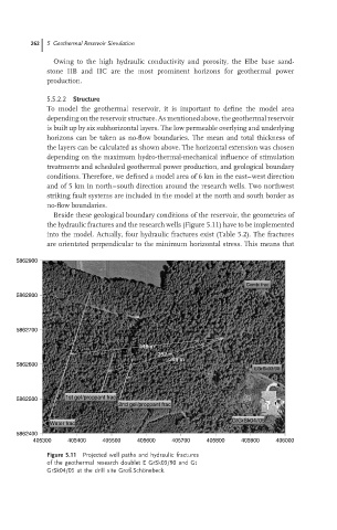
Beside these geological boundary conditions of the reservoir, the geometries of
the hydraulic fractures and the research wells (Figure 5.11) have to be implemented
into the model. Actually, four hydraulic fractures exist (Table 5.2). The fractures
are orientated perpendicular to the minimum horizontal stress. This means that
5862900
Combi frac
5862800
5862700
448 m
352 m
308 m
5862600
EGrSk03/90
5862500 1st gel/proppant frac
2nd gel/proppant frac
GtGrSk04/05
Water frac
5862400
405300 405400 405500 405600 405700 405800 405900 406000
Figure 5.11 Projected well paths and hydraulic fractures
of the geothermal research doublet E GrSk03/90 and Gt
..
GrSk04/05 at the drill site Groß Schonebeck.