
Page 287 - Geothermal Energy Systems Exploration, Development, and Utilization
P. 287
5.5 Groß Sch¨ onebeck 263
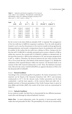
Table 5.1 Hydraulic and thermal properties of the reservoir
rocks under in situ conditions. The hydraulic conductivity was
estimated by means of a reference dynamic viscosity of 0.3
−1
◦
mPa·s(at T = 150 Cand C = 265 g l ).
Layer k k K n T λ c
−1
−1
−1
◦
2
(mD) (m ) (m s ) (%) ( ) [W (mK) ] [J (kg K) ]
I 0.05 4.93E-17 1.34E-09 1 138.2 1.9 920
IIA 2 1.97E-15 5.37E-08 3 141.7 1.9 920
IIB 4 3.95E-15 1.07E-07 8 143.2 2.9 920
IIC 8 7.90E-15 2.15E-07 15 145.2 2.8 920
III 0.1 9.87E-17 2.68E-09 0.1 146.5 3.0 1000
IV 0.1 9.87E-17 2.68E-09 0.5 147.4 2.3 1380
for the recent in situ stress field an azimuth of 18 is required. The arrangement
◦
of the two wells has to fulfill two important conditions. First, the wells should be
located in such a way that the pressure in the reservoir would not drop significantly
during production, and second, a temperature drop in the production well should
be avoided. At the surface the two wells have a distance of 28 m. Owing to the fact
that the well E GrSK3/90 is vertically orientated and to ensure a distance of 500 m
within the reservoir, the second well Gt GrSk4/05 is drilled as a deviated well. At
◦
the top of the reservoir (−3850 m) the inclination is 18 and increases progressively
◦
to 48 at −4200 m. Therefore, the distance between the two wells increases from
254 to 473 m from the top to the bottom of the reservoir (Figure 5.11). Besides the
realization of the required distance within the reservoir, the deviation leads to an
increase of the well–reservoir intersection as well. Thus, the thickness increases
from 350 m for the vertical well E GrSK3/90 to an apparent thickness of 442 m for
the deviated well Gt GrSk4/05.
5.5.2.3 Thermal Conditions
According to the continental geothermal gradient, the lowest temperature of the
◦
reservoir can be found at the Hannover formation with 138 Cand increases
◦
continuously to 147 C for the volcanic rocks. Further parameters are the heat
conductivity λ and the heat capacity c of the reservoir fluid and solid rock. A
detailed overview of thermal parameters of the North German basin is given by
Lotz (2004) and Gehrke (2007); the results of the latter work are summarized in
Table 5.1.
5.5.2.4 Hydraulic Conditions
In our reservoir model, the fluid flow is characterized by two different processes:
matrix flow and drainage by induced hydraulic fractures.
Matrix Flow In most sedimentary rocks, the porosity is interconnected, which
makes the rock permeable for flow. The permeability of a rock can be measured by