
Page 309 - Geothermal Energy Systems Exploration, Development, and Utilization
P. 309
5.9 KTB (Germany) 285
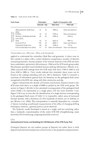
Table 5.3 Fault zones of the KTB site.
Fault Zones Orientation Depth of intersection with
Azimuth Dip Main hole Pilot hole
Altenparkstein Fault Zone 45 52 7000 m Does not intersect
line (SEI) 45 41 4750 m Does not intersect
0.5SE1a
Fraconian Waldeck–Klobenreuth fault 45 41 3500 m 3326 m
zone (SE2)
3997 m
SE2a
4225 m
45
55
Erbendorf line 120 54 6000 m Does not intersect
Nottersdorf fault zone 60 65 1100 m 721 m
Fichtelnaab fault zone (SE4) 15 52 Does not intersect a Does not intersect
a Closest surface trace +900 m east, +900 m north of main hole.
applied to understand the subsurface fluid flow and geometry. A shear zone in
this context is a plane with a certain thickness comprising a number of discrete
interacting fractures. Several analyses of the tectonic features at the KTB site have
been undertaken, particularly (Hirschmann, 1996) and the KTB work group under
Hirschmann provided much detailed fracture picking information. (Winter et al.,
2002) analyzed drill cuttings from the KTB main hole from 1700 to 2400 m and
from 4500 to 5000 m. Their results indicate that cataclastic shear zones can be
found in the cuttings extending well over 100 m thickness. Table 5.3 presents a
summary of information gained from the literature on the geological fault zones
recognized at the KTB site, along with their orientation and dip.
Figure 5.28 presents the density of fractures and tectonic features found in the
KTB main hole down to a depth of 8000 m picked by the KTB work group. The
arrows in Figure 5.28 refer to the calculated crossing points of the geological fault
zones (Table 5.3) represented as a single plane with the main borehole. From
Figure 5.28 it canbeseen that theidentification of asinglefracturecorresponding
to the geological fault zones of Table 5.3 is impossible, rather areas of increased
fracture density, with a thickness of a few hundreds of meters can be defined, as
per (Winter et al., 2002). This interpretation is naturally dependent on a number
of factors including uncalibrated measurements of the effect of changing drilling
techniques; however, a general pattern can be observed.
The hydraulic model developed is based on a single well test matching rather
than a hydraulic characterization of the entire KTB HB (Hauptbohrung, main
borehole)-VB (Vorbohrung, preparing borehole) reservoir.
5.9.2
Geomechanical Facies and Modeling the HM Behavior of the KTB Pump Test
Geological deposits are not random groups of deposits but rather there is both
depositional and structural process control on the in situ properties and parameters.