
Page 310 - Geothermal Energy Systems Exploration, Development, and Utilization
P. 310
286 5 Geothermal Reservoir Simulation
Undisturbed zone Pilot borehole
Damage around shear zone
Geomechanical facies Core of shear zone SE2a
section
Open hole
Damage around shear zone
Undisturbed zone Fracture Rock
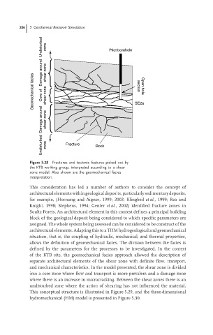
Figure 5.28 Fractures and tectonic features picked out by
the KTB working group, interpreted according to a shear
zone model. Also shown are the geomechanical facies
interpretation.
This consideration has led a number of authors to consider the concept of
architecturalelements withingeologicaldeposits,particularlysedimentarydeposits,
for example, (Hornung and Aigner, 1999; 2002; Klingbeil et al., 1999; Rea and
Knight, 1998; Stephens, 1994; Genter et al., 2002) identified fracture zones in
Soultz Forets. An architectural element in this context defines a principal building
block of the geological deposit being considered to which specific parameters are
assigned. The whole system being assessed can be considered to be construct of the
architectural elements. Adapting this to a THM hydrogeological and geomechanical
situation, that is, the coupling of hydraulic, mechanical, and thermal properties,
allows the definition of geomechanical facies. The division between the facies is
defined by the parameters for the processes to be investigated. In the context
of the KTB site, the geomechanical facies approach allowed the description of
separate architectural elements of the shear zone with definite flow, transport,
and mechanical characteristics. In the model presented, the shear zone is divided
into a core zone where flow and transport is more prevalent and a damage zone
where there is an increase in microcracking. Between the shear zones there is an
undisturbed zone where the action of shearing has not influenced the material.
This conceptual structure is illustrated in Figure 5.29, and the three-dimensional
hydromechanical (HM) model is presented in Figure 5.30.