
Page 175 - Glucose Monitoring Devices
P. 175
Calibration of minimally invasive CGM sensors 177
(A) (B)
FIGURE 9.3
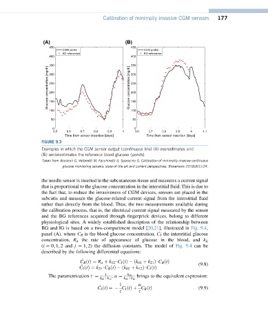
Examples in which the CGM sensor output (continuous line) (A) overestimates and
(B) underestimates the reference blood glucose (points).
Taken from Acciaroli G, Vettoretti M, Facchinetti A, Sparacino G. Calibration of minimally invasive continuous
glucose monitoring sensors: state-of-the-art and current perspectives. Biosensors 2018;8(1):24.
the needle sensor is inserted in the subcutaneous tissue and measures a current signal
that is proportional to the glucose concentration in the interstitial fluid. This is due to
the fact that, to reduce the invasiveness of CGM devices, sensors are placed in the
subcutis and measure the glucose-related current signal from the interstitial fluid
rather than directly from the blood. Thus, the two measurements available during
the calibration process, that is, the electrical current signal measured by the sensor
and the BG references acquired through fingerprick devices, belong to different
physiological sites. A widely established description of the relationship between
BG and IG is based on a two-compartment model [20,21], illustrated in Fig. 9.4,
panel (A), where C B is the blood glucose concentration, C I the interstitial glucose
concentration, R a the rate of appearance of glucose in the blood, and k ij
(i ¼ 0; 1; 2 and j ¼ 1; 2) the diffusion constants. The model of Fig. 9.4 can be
described by the following differential equations:
C B ðtÞ¼ R a þ k 12 $C I ðtÞ ðk 01 þ k 21 Þ$C B ðtÞ (9.8)
C I ðtÞ¼ k 21 $C B ðtÞ ðk 02 þ k 12 Þ$C I ðtÞ
1 k 21
The parametrization s ¼ , a ¼ brings to the equivalent expression:
k 02 þk 12 k 02 þk 12
1
a
C I ðtÞ¼ C I ðtÞþ C B ðtÞ (9.9)
s s