
Page 193 - HVAC Pump Handbook
P. 193
Rishel_07.qxd 20/4/06 6:29 PM Page 190
Pump Drivers and Variable-Speed Drives
190 HVAC Pumps and Their Performance
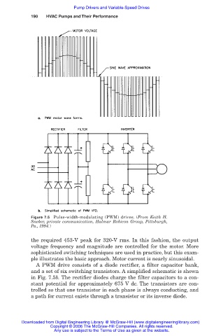
Figure 7.5 Pulse-width-modulating (PWM) drives. (From Keith H.
Sneker, private communication, Halmar Robicon Group, Pittsburgh,
Pa., 1994.)
the required 453-V peak for 320-V rms. In this fashion, the output
voltage frequency and magnitude are controlled for the motor. More
sophisticated switching techniques are used in practice, but this exam-
ple illustrates the basic approach. Motor current is nearly sinusoidal.
A PWM drive consists of a diode rectifier, a filter capacitor bank,
and a set of six switching transistors. A simplified schematic is shown
in Fig. 7.5b. The rectifier diodes charge the filter capacitors to a con-
stant potential for approximately 675 V dc. The transistors are con-
trolled so that one transistor in each phase is always conducting, and
a path for current exists through a transistor or its inverse diode.
Downloaded from Digital Engineering Library @ McGraw-Hill (www.digitalengineeringlibrary.com)
Copyright © 2006 The McGraw-Hill Companies. All rights reserved.
Any use is subject to the Terms of Use as given at the website.