
Page 195 - HVAC Pump Handbook
P. 195
Rishel_07.qxd 20/4/06 6:29 PM Page 192
Pump Drivers and Variable-Speed Drives
192 HVAC Pumps and Their Performance
Medium-voltage drives. Medium-voltage drives (2300 and 4000 V)
have become available for large chilled water pumps with horse-
power ratings of 750 hp and larger. These motors can be synchro-
nous or induction types. Smaller motors may be economically feasible
for medium voltages if the chillers are equipped with medium-voltage
motors.
It is obvious that motors of this size and type need quality drives to
achieve the efficiency and reliability required for such large installa-
tions. The complexity of these drives necessitates that they be evalu-
ated and selected by an electrical engineer experienced in variable
speed drive technology.
A detailed paper evaluating most of the current types of medium-volt-
age drives has been provided by Mr. Richard H. Osman, Vice President
of Technology for Robicon titled “Medium–Voltage Variable
Frequency Drives for Induction and Synchronous Motors.” This is an
important document that should be studied by electrical engineers
involved in large chiller plant design.
The following is a condensation of this material that describes the
four types of medium-voltage drives that may be encountered in the
HVAC industry.
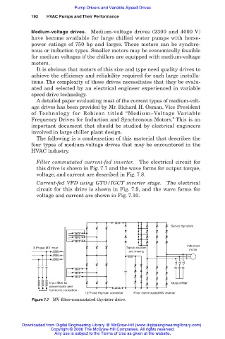
Filter commutated current-fed inverter. The electrical circuit for
this drive is shown in Fig. 7.7 and the wave forms for output torque,
voltage, and current are described in Fig. 7.8.
Current-fed VFD using GTO/IGCT inverter stage. The electrical
circuit for this drive is shown in Fig. 7.9, and the wave forms for
voltage and current are shown in Fig. 7.10.
Series thyristors
Induction
3-Phase MV input Typical snubber motor
and sharing
Input filter for Output filter
power factor and
harmonic correction
12 Pulse thyrister converter Filter commutated MV inverter
Figure 7.7 MV filter-commutated thyrister drive.
Downloaded from Digital Engineering Library @ McGraw-Hill (www.digitalengineeringlibrary.com)
Copyright © 2006 The McGraw-Hill Companies. All rights reserved.
Any use is subject to the Terms of Use as given at the website.