
Page 198 - HVAC Pump Handbook
P. 198
Rishel_07.qxd 20/4/06 6:29 PM Page 195
Pump Drivers and Variable-Speed Drives
Pump Drivers and Variable-Speed Drives 195
2.0
1.5
1.0
Voltage in pu −0.5 0 0.002 0.004 0.006 0.008 0.01 0.012 0.014 0.016 0.018 0.02
0.5
0.0
−1.0
−1.5
−2.0
Time in s
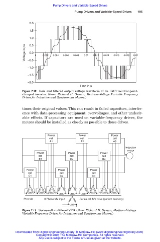
Figure 7.12 Raw and filtered output voltage waveform of an IGCT neutral-point-
clamped inverter. (From Richard H. Osman, Medium–Voltage Variable Frequency
Drives for Induction and Synchronous Motors.)
times their original values. This can result in failed capacitors, interfer-
ence with data-processing equipment, overvoltages, and other undesir-
able effects. If capacitors are used on variable-frequency drives, the
motors should be installed as closely as possible to those drives.
Power Power Power
cell cell cell
A1 A2 A3
Induction
motor
Power Power Power
cell cell cell
B1 B2 B3
Power Power Power
cell cell cell
C1 C2 C3
Phrmckt 3 Phase MV input Series cell MV drive (perfect harmony)
Figure 7.13 Series-cell multilevel VFD. (From Richard H. Osman, Medium–Voltage
Variable Frequency Drives for Induction and Synchronous Motors.)
Downloaded from Digital Engineering Library @ McGraw-Hill (www.digitalengineeringlibrary.com)
Copyright © 2006 The McGraw-Hill Companies. All rights reserved.
Any use is subject to the Terms of Use as given at the website.