
Page 196 - HVAC Pump Handbook
P. 196
Rishel_07.qxd 20/4/06 6:29 PM Page 193
Pump Drivers and Variable-Speed Drives
Pump Drivers and Variable-Speed Drives 193
T T T
l l l
V
V V
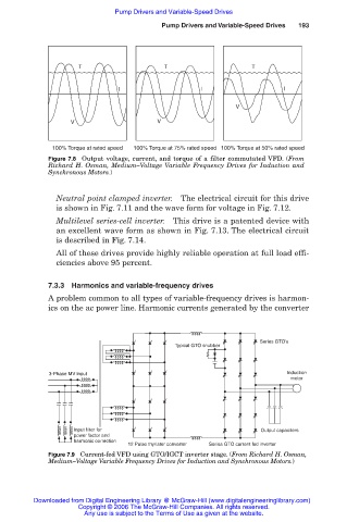
100% Torque at rated speed 100% Torque at 75% rated speed 100% Torque at 50% rated speed
Figure 7.8 Output voltage, current, and torque of a filter commutated VFD. (From
Richard H. Osman, Medium–Voltage Variable Frequency Drives for Induction and
Synchronous Motors.)
Neutral point clamped inverter. The electrical circuit for this drive
is shown in Fig. 7.11 and the wave form for voltage in Fig. 7.12.
Multilevel series-cell inverter. This drive is a patented device with
an excellent wave form as shown in Fig. 7.13. The electrical circuit
is described in Fig. 7.14.
All of these drives provide highly reliable operation at full load effi-
ciencies above 95 percent.
7.3.3 Harmonics and variable-frequency drives
A problem common to all types of variable-frequency drives is harmon-
ics on the ac power line. Harmonic currents generated by the converter
Series GTO’s
Typical GTO snubber
3-Phase MV input Induction
motor
Input filter for Output capaciters
power factor and
harmonic correction
12 Pulse thyrister converter Series GTO current fed inverter
Figure 7.9 Current-fed VFD using GTO/IGCT inverter stage. (From Richard H. Osman,
Medium–Voltage Variable Frequency Drives for Induction and Synchronous Motors.)
Downloaded from Digital Engineering Library @ McGraw-Hill (www.digitalengineeringlibrary.com)
Copyright © 2006 The McGraw-Hill Companies. All rights reserved.
Any use is subject to the Terms of Use as given at the website.