
Page 427 - Hacking Roomba
P. 427
408 Appendix B — Electrical Diagram Schematics
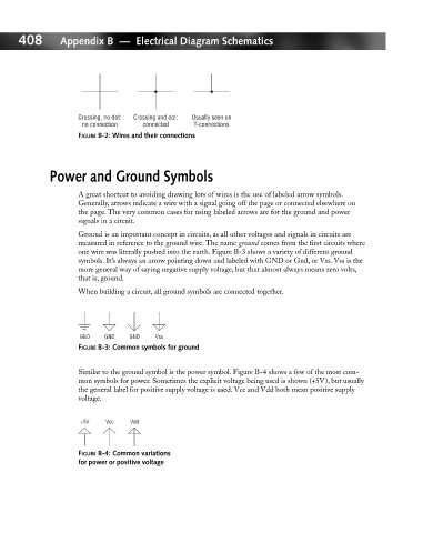
Crossing, no dot: Crossing and dot: Usually seen on
no connection connected T-connections
FIGURE B-2: Wires and their connections
Power and Ground Symbols
A great shortcut to avoiding drawing lots of wires is the use of labeled arrow symbols.
Generally, arrows indicate a wire with a signal going off the page or connected elsewhere on
the page. The very common cases for using labeled arrows are for the ground and power
signals in a circuit.
Ground is an important concept in circuits, as all other voltages and signals in circuits are
measured in reference to the ground wire. The name ground comes from the first circuits where
one wire was literally pushed into the earth. Figure B-3 shows a variety of different ground
symbols. It’s always an arrow pointing down and labeled with GND or Gnd, or Vss. Vss is the
more general way of saying negative supply voltage, but that almost always means zero volts,
that is, ground.
When building a circuit, all ground symbols are connected together.
GND GND GND Vss
FIGURE B-3: Common symbols for ground
Similar to the ground symbol is the power symbol. Figure B-4 shows a few of the most com-
mon symbols for power. Sometimes the explicit voltage being used is shown (+5V), but usually
the general label for positive supply voltage is used. Vcc and Vdd both mean positive supply
voltage.
+5V Vcc Vdd
FIGURE B-4: Common variations
for power or positive voltage