
Page 428 - Hacking Roomba
P. 428
Appendix B — Electrical Diagram Schematics 409
The Vdd and Vss labels come from the MOSFET transistor that enabled high-density inte-
grated circuits. A MOSFET has a drain (positive pin) and a source (negative pin). Vdd meant
the voltage for all drain pins, and Vss meant the same for all source pins. The Vcc label comes
from the earlier BJT transistor type that had collector and emitter pins instead of drain and
source. As you might expect, there is a Vee label to go along with the Vcc, but today it’s more
common to use Gnd instead.
A circuit may have multiple voltage sources, each distinct from one another. For example, in
the Roomba adapter schematics you see Vpwr or +16VDC to indicate the power from Roomba
and Vcc+ or +5VDC to indicate the regulated power coming from the 7805 voltage regulator.
When building a circuit, all power symbols with the same value are connected together.
Basic Components
When you have power and ground, you can start hooking up components between the two to
do things. Simple components like resistors and capacitors are considered passive since they do
not require a source of energy to perform their task. Passive components usually have two leads
(also known as pins or terminals). They are the simplest parts physically but often have the
most interesting symbols. In contrast, active components like integrated circuits (ICs) require
power and have complex internal functionality, but are represented by simple rectangles bris-
tling with short lines indicating their connection pins.
Resistors
Resistors are the most basic of components. They are commonly used to limit the amount of
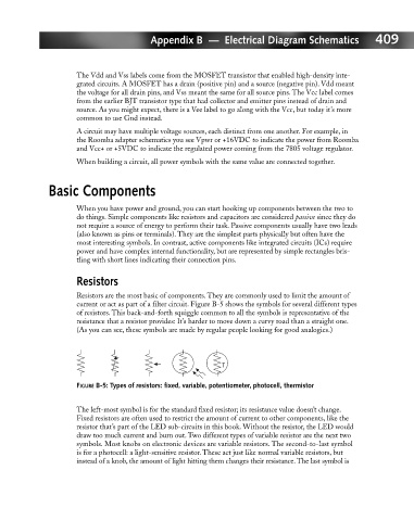
current or act as part of a filter circuit. Figure B-5 shows the symbols for several different types
of resistors. This back-and-forth squiggle common to all the symbols is representative of the
resistance that a resistor provides: It’s harder to move down a curvy road than a straight one.
(As you can see, these symbols are made by regular people looking for good analogies.)
T
FIGURE B-5: Types of resistors: fixed, variable, potentiometer, photocell, thermistor
The left-most symbol is for the standard fixed resistor; its resistance value doesn’t change.
Fixed resistors are often used to restrict the amount of current to other components, like the
resistor that’s part of the LED sub-circuits in this book. Without the resistor, the LED would
draw too much current and burn out. Two different types of variable resistor are the next two
symbols. Most knobs on electronic devices are variable resistors. The second-to-last symbol
is for a photocell: a light-sensitive resistor. These act just like normal variable resistors, but
instead of a knob, the amount of light hitting them changes their resistance.The last symbol is