
Page 429 - Hacking Roomba
P. 429
410 Appendix B — Electrical Diagram Schematics
for a thermistor, a resistor that changes its resistance value based on the temperature.Thermistors
are sometimes used in thermostats for heaters and air conditioners. New types of variable
resistors are created all the time (bend-sensitive, force-sensitive, and so on), and so new sym-
bols are also created.
Capacitors
Capacitors store small amounts of electricity and are useful as parts of filters or to smooth out
power supply fluctuations. The amount of electricity a capacitor can store is its charge capacity,
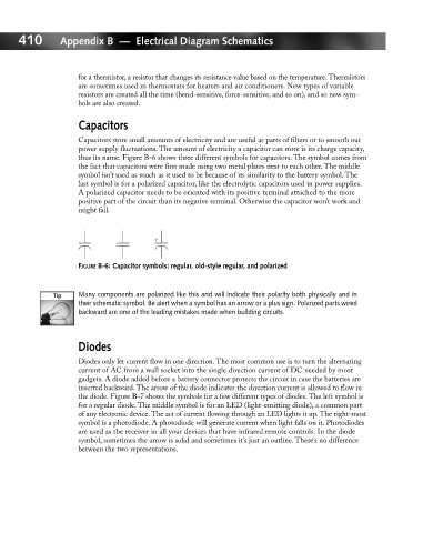
thus its name. Figure B-6 shows three different symbols for capacitors. The symbol comes from
the fact that capacitors were first made using two metal plates next to each other. The middle
symbol isn’t used as much as it used to be because of its similarity to the battery symbol. The
last symbol is for a polarized capacitor, like the electrolytic capacitors used in power supplies.
A polarized capacitor needs to be oriented with its positive terminal attached to the more
positive part of the circuit than its negative terminal. Otherwise the capacitor won’t work and
might fail.
+
FIGURE B-6: Capacitor symbols: regular, old-style regular, and polarized
Many components are polarized like this and will indicate their polarity both physically and in
their schematic symbol. Be alert when a symbol has an arrow or a plus sign. Polarized parts wired
backward are one of the leading mistakes made when building circuits.
Diodes
Diodes only let current flow in one direction. The most common use is to turn the alternating
current of AC from a wall socket into the single direction current of DC needed by most
gadgets. A diode added before a battery connector protects the circuit in case the batteries are
inserted backward. The arrow of the diode indicates the direction current is allowed to flow in
the diode. Figure B-7 shows the symbols for a few different types of diodes. The left symbol is
for a regular diode. The middle symbol is for an LED (light-emitting diode), a common part
of any electronic device. The act of current flowing through an LED lights it up. The right-most
symbol is a photodiode. A photodiode will generate current when light falls on it. Photodiodes
are used as the receiver in all your devices that have infrared remote controls. In the diode
symbol, sometimes the arrow is solid and sometimes it’s just an outline. There’s no difference
between the two representations.