
Page 244 - Handbook Of Multiphase Flow Assurance
P. 244
Hydrate stability and crystal growth 243
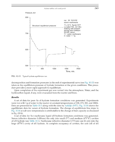
Pressure, torr
800
run 39 10/9/92
xenon–neohexane
Structure I equilibrium pressure T=–10°C, Tamb=75°F
s.s.balls=150, D=1/8in.
shaking rate=970rpm
stirring rate=1000rpm
99.999 xenon
700 7:1 water–neohexane
m water = 1g
600
500
0 500 1000 1500 2000
Time, min.
FIG. 10.15 Typical hydrate equilibrium run.
decomposition and formation pressures in the end of experimental curve (see Fig. 10.13) was
taken as the equilibrium pressure of hydrate formation at the given conditions. This proce-
dure provides a more rapid approach to equilibrium.
Upon completion of the experiment gas was vented into the atmosphere. Water, and the
hydrocarbon liquid, if any, were evacuated from the reactor and lines.
Results
A set of data for pure Xe sI hydrate formation conditions was generated. Experiments
were run with 1 g of water in the reactor at constant temperatures of 228, 273, 283, and 288 K.
Data are presented in Table 10.3 along with the data by Aaldijk (1971). Fig. 10.16 shows the
equilibrium data for xenon sI hydrate formation. The change of equilibrium line slope in
Fig. 10.16 at sub-zero temperatures is attributable to the change of heat capacity as discussed
in Eq. (10.6).
A set of data for Xe + neohexane liquid sH hydrate formation conditions was generated.
12
3 12 3
Xenon (effective diameter 0.458 nm) fits only into small (5 ) and medium (4 5 6 ) cavities
of sH hydrate (see Table 10.1). Neohexane (effective diameter 0.773 nm) can fit only into the
3 6 3
large (4 5 6 ) cavity of sH hydrate. At complete occupancy of cavities, the unit cell of sH