Page 61 - Handbook of Electrical Engineering
P. 61

40    HANDBOOK OF ELECTRICAL ENGINEERING

              which may be represented by a simple linear function,

                                                  ω = ω o − kT                               (2.47)

              where k is a positive number in the order of 1.0 pu equal to the open-loop slope, and ω o is the shaft
              speed at no-load.
                    Reference 7 discusses the slope k in Chapter 2, Section 2.3.1.
                    Assume that the turbine is designed to deliver unit torque at unit speed, therefore,

                                            1.0 = ω o − k(1.0) = ω o − k                     (2.48)

              From which ω o = 1 + k and so (2.47) becomes,

                                                              1 + k − ω
                                         ω = 1 + k − kT or T =                               (2.49)
                                                                  k
              The speed can now be related to the shaft power rather than the torque,

                                                     1 + k − ω
                                               P =              ω                            (2.50)
                                                         k
              Or in the form of a quadratic equation,

                                                   2
                                              0 = ω − (1 + k)ω + kP                          (2.51)
              The two roots of which are,

                                                             2
                                              1 + k     (1 + k) − 4kP    1/2
                                        ω 1,2 =     ±                                        (2.52)
                                                2            2
                    The positive root applies to the stable operating region, whilst the negative root applies to the
              unstable region after stalling occurs.
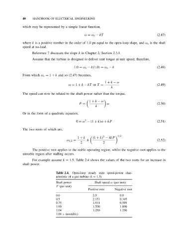
                    For example assume k = 1.5. Table 2.4 shows the values of the two roots for an increase in
              shaft power.

                                  Table 2.4.  Open-loop steady state speed-power char-
                                  acteristic of a gas turbine (k = 1.5)
                                  Shaft power           Shaft speed ω (per unit)
                                  P (per unit)
                                                     Positive root  Negative root
                                  0.0                  2.5             0.0
                                  0.5                  2.151           0.349
                                  0.75                 1.911           0.589
                                  1.00                 1.500           1.000
                                  1.04                 1.250           1.250
                                  1.04 + (unstable)
   56   57   58   59   60   61   62   63   64   65   66