
Page 62 - Handbook of Electrical Engineering
P. 62
GAS TURBINE DRIVEN GENERATORS 41
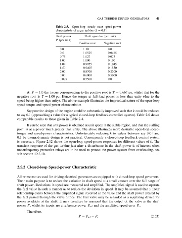
Table 2.5. Open-loop steady state speed-power
characteristic of a gas turbine (k = 0.1)
Shaft power Shaft speed ω (per unit)
P (per unit)
Positive root Negative root
0.0 1.10 0.0
0.5 1.0525 0.0475
0.75 1.027 0.073
1.00 1.000 0.100
1.04 0.9955 0.1045
1.50 0.9405 0.1550
2.00 0.8700 0.2300
3.00 0.6000 0.5000
3.025 0.5500 0.0
At P = 1.0 the torque corresponding to the positive root is T = 0.667 pu, whilst that for the
negative root is T = 1.00 pu. Hence the torque at full-load power is less than unity (due to the
speed being higher than unity). The above example illustrates the impractical nature of the open-loop
speed-torque and speed-power characteristics.
Suppose the design of the engine could be substantially improved such that k could be reduced
to say 0.1 (approaching a value for a typical closed-loop feedback controlled system). Table 2.5 shows
comparable results to those given in Table 2.4.
It can be seen that unit power is obtained at unit speed in the stable region, and that the stalling
point is at a power much greater than unity. The above illustrates more desirable open-loop speed-
torque and speed-power characteristics. Unfortunately reducing k to values between say 0.01 and
0.1 by thermodynamic design is not practical. Consequently a closed-loop feedback control system
is necessary. Figure 2.12 shows the open-loop speed-power responses for different values of k.The
transient response of the gas turbine just after a disturbance in the shaft power is of interest when
underfrequency protective relays are to be used to protect the power system from overloading, see
sub-section 12.2.10.
2.5.2 Closed-loop Speed-power Characteristic
All prime-moves used for driving electrical generators are equipped with closed-loop speed governors.
Their main purpose is to reduce the variation in shaft speed to a small amount over the full range of
shaft power. Deviations in speed are measured and amplified. The amplified signal is used to operate
the fuel value in such a manner as to reduce the deviation in speed. It may be assumed that a linear
relationship exists between the amplified signal received at the value and the shaft power created by
the fuel passed through the valve orifice. The fuel valve may be regarded as a regulating device for
power available at the shaft. It may therefore be assumed that the output of the valve is the shaft
power P , whilst its inputs are a reference power P ref and the amplified speed error P e .
Therefore,
P = P ref − P e (2.53)