Page 66 - Handbook of Electrical Engineering
P. 66

GAS TURBINE DRIVEN GENERATORS      45


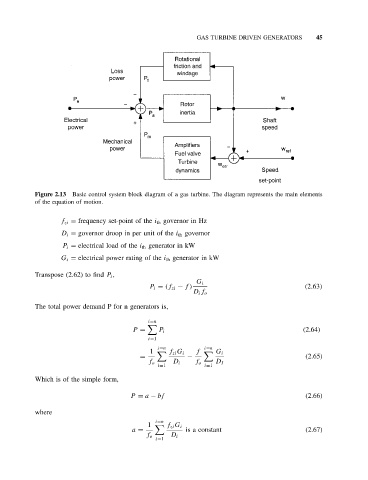
           Figure 2.13 Basic control system block diagram of a gas turbine. The diagram represents the main elements
           of the equation of motion.


                   f zi = frequency set-point of the i th governor in Hz
                   D i = governor droop in per unit of the i th governor
                   P i = electrical load of the i th generator in kW
                   G i = electrical power rating of the i th generator in kW

           Transpose (2.62) to find P i ,
                                                          G i
                                            P i = (f zi − f)                              (2.63)
                                                         D i f o
           The total power demand P for n generators is,

                                            i=n

                                        P =    P i                                       (2.64)
                                            i=1
                                               i=n           i=n
                                             1  	  f zi G i  f  	  G i
                                          =            −                                  (2.65)
                                            f o    D i    f o   D I
                                               i=1           i=1
           Which is of the simple form,

                                       P = a − bf                                         (2.66)

           where
                                              i=n
                                            1  	  f zi G i
                                       a =             is a constant                      (2.67)
                                            f o    D i
                                              i=1
   61   62   63   64   65   66   67   68   69   70   71