Page 291 - Handbook of Materials Failure Analysis
P. 291

5 Material and Experiment   287


                             1200


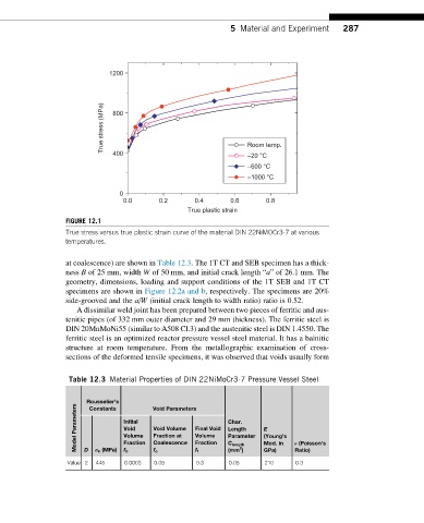
                           True stress (MPa)  800               Room temp.


                              400
                                                                –20 °C
                                                                –600 °C
                                                                –1000 °C
                               0
                                0.0      0.2       0.4      0.6      0.8
                                                 True plastic strain
                  FIGURE 12.1
                  True stress versus true plastic strain curve of the material DIN 22NiMOCr3-7 at various
                  temperatures.

                  at coalescence) are shown in Table 12.3. The 1T CT and SEB specimen has a thick-
                  ness B of 25 mm, width W of 50 mm, and initial crack length “a” of 26.1 mm. The
                  geometry, dimensions, loading and support conditions of the 1T SEB and 1T CT
                  specimens are shown in Figure 12.2a and b, respectively. The specimens are 20%
                  side-grooved and the a/W (initial crack length to width ratio) ratio is 0.52.
                     A dissimilar weld joint has been prepared between two pieces of ferritic and aus-
                  tenitic pipes (of 332 mm outer diameter and 29 mm thickness). The ferritic steel is
                  DIN 20MnMoNi55 (similar to A508 Cl.3) and the austenitic steel is DIN 1.4550. The
                  ferritic steel is an optimized reactor pressure vessel steel material. It has a bainitic
                  structure at room temperature. From the metallographic examination of cross-
                  sections of the deformed tensile specimens, it was observed that voids usually form


                   Table 12.3 Material Properties of DIN 22NiMoCr3-7 Pressure Vessel Steel


                       Rousselier’s     Void Parameters
                    Parameters  Initial  Void Volume  Final Void  Char.  E
                        Constants
                                Void
                                                           Length
                    Model  D  σ k (MPa)  Volume  Fraction at  Volume  Parameter  (Young’s  ν (Poisson’s
                                Fraction
                                        Coalescence
                                                   Fraction
                                                                    Mod. in
                                                           C length
                                                              2
                                                                    GPa)
                                                                            Ratio)
                                                           (mm )
                                f 0
                                        f c
                                                   f f
                  Value 2  445   0.0003  0.05      0.3     0.05     210     0.3
   286   287   288   289   290   291   292   293   294   295   296