
Page 292 - Handbook of Materials Failure Analysis
P. 292
288 CHAPTER 12 A nonlocal damage-mechanics-based approach
B
F
B n
W
F
V LL
W
a
a 0
L = 4W
(a) (b) F
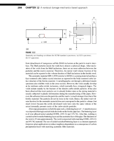
FIGURE 12.2
Geometry and loading conditions for ASTM standard specimens. (a) SEB specimen;
(b) CT specimen.
from detachment of manganese sulfide (MnS) inclusions at the particle-matrix inter-
face. The MnS particles inside the voids have almost a spherical shape. After nucle-
ation of the voids from the MnS inclusions, there are no more adhesion between the
particles and the matrix material. Therefore, the initial void volume fraction of the
material can be equated to the volume fraction of MnS inclusions in the ferritic steel.
The austenitic material DIN 1.4550 (similar to SS304) is a piping material and has a
face-centered cubic lattice crystal structure as opposed to the body-centered cubic lat-
tice structure of the ferritic material. A metallographic cut through a deformed tensile
specimen also exhibits voids in the cross-section. However, the voids usually develop
at the niobium carbo-nitride inclusions, which normally have elongated shapes. The
voids initiate mainly by the fracture of the slender carbo-nitride particles. It has also
been observed that most particles are in already broken state as the piping material is
usually subjected to plastic deformation during the manufacturing of the pipes. How-
ever, the adhesion between the particles and the matrix is much stronger than that of the
ferritic material. The particles do not lie loose in the voids. Hence, the initial void vol-
ume fraction for the austenitic material does not correspond to the particle volume (but
much lower) because the newly developed voids have only the same volume of the
actual internally present cracks of the carbo-nitride particles.
Afteredgepreparationsonboththepipeends,abutteringlayer(of 4 mmthickness)
wasdepositedthroughanickel-richelectrodeontheferriticpipeface.Thebutteringlayer
is of over-alloyed nickel-enriched E309L (24% Cr and 12% Ni). After this, welding is
carriedoutbetweenthebutteringlayerandtheausteniticfaceofthepipe.Thethicknessof
the weld is 25 mm approximately. The weld is deposited with matching E308L (18% Cr
and 8% Ni) material. The use of nickel-enriched buttering layer is a common approach
forpower-plantapplicationstoreducetoughnessdegradationasaconsequenceofcarbon
precipitation faced with matching austenitic filler materials.