
Page 293 - Handbook of Materials Failure Analysis
P. 293
5 Material and Experiment 289
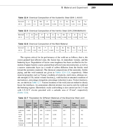
Table 12.4 Chemical Composition of the Austenitic Steel (DIN 1.4550)
Element C Si Mn P S Cr Ni Mo Nb Fe
Wt.% 0.045 0.3 1.89 0.028 0.004 17.6 10.6 0.28 0.45 Rest
Table 12.5 Chemical Composition of the Ferritic Steel (DIN 20MnMoNo55)
Element C Si Mn P S Cr Ni Mo V Al Cu Fe
Wt.% 0.21 0.21 1.3 0.009 0.001 0.05 0.068 0.494 0.01 0.029 0.02 Rest
Table 12.6 Chemical Composition of the Weld Material
Element C Si Mn P S Cr Ni Mo Nb Ti Fe
Wt.% 0.025 0.38 4.81 0.01 0.005 18.2 Rest 1.3 2.17 0.06 3.48
The regions critical for the performance of the weld are as follows, that is, the
coarse-grained heat-affected zone, the fusion line, its immediate vicinity, and the
buttering layer. Degradation of fusion zone toughness has been ascribed to the for-
mation of upper-bainitic coarse-grained heat-affected zone microstructure, as well as
a narrow martensitic layer (as a result of carbon diffusion from the ferritic steel
toward the austenitic material). The chemical compositions of the austenitic, ferritic
piping, and the weld material are given in Tables 12.4–12.6, respectively. Other
material properties such as Young’s modulus of elasticity, yield stress, ultimate ten-
sile strength (UTS), initial volume fraction f 0 , void fraction at saturated condition of
nucleation f n , percentage elongation, percentage reduction in area, Vickers hardness,
etc. are shown in Table 12.7. Various locations of the weld joint are etched to clearly
locate the interfaces. An ammonium chloride mixture was used to etch the weld and
the buttering regions. Electrolytic oxalic acid etching is also carried out for 2-3 min
2
with 1.5-3.0 V electric potential with a cathodic area of 25 mm , respectively
(Table 12.6).
Table 12.7 Parameters for Different Materials of the Dissimilar Weld Joint
Initial Void Fraction
Young’s Yield Void at Saturated %age
Modulus Stress UTS Fraction Nucleation %age Reduction Vickers
Material (MPa) (MPa) (MPa) f 0 Condition f n Elongation in Area Hardness
Austenitic 1.94E5 245 588 0.000001 0.0055 68.1 73.9 153
steel
Ferritic 2.271E5 536.4 675 0.005 0.008 25.1 74.1 160
steel
Weld 1.82E5 448.1 587 0.001 0.008 14.2 17.9 234
material
Buttering 2.0455E5 417.83 631 0.004 0 14.8 18.5 228
material