
Page 22 - Handbook of Structural Steel Connection Design and Details
P. 22
Fasteners and Welds for Structural Connections
Fasteners and Welds for Structural Connections 7
Either the head or the nut can be the element turned. Paint of any type
is permitted on the faying surfaces.
Threads excluded from shear planes. The bearing-type connection with
threads excluded from shear planes is the most economical high-strength
bolted connection, because fewer bolts generally are needed for a given
required strength. There can be difficulties involved in excluding the
threads from the shear planes when either one or both of the outer plies
of the joint is thin. The location of the thread runout or vanish depends
on which side of the connection the bolt is entered and whether a washer
is placed under the head or the nut. This location is difficult to control
in the shop but even more so in the field. However, since for a given diam-
eter of bolt the thread length is constant, threads can often be excluded
in heavy joints with no additional effort.
Total nominal thread lengths and vanish thread lengths for high-
strength bolts are given in Table 1.1. It is common practice to allow the
last ⁄8 in of vanish thread to extend across a single shear plane.
1
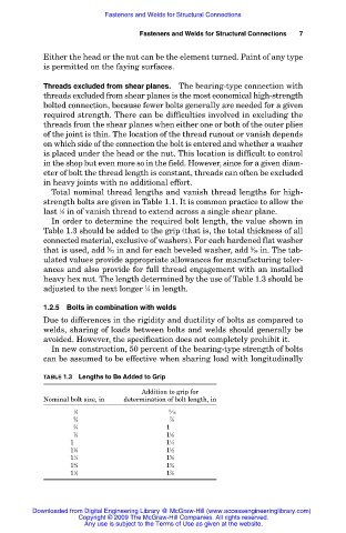
In order to determine the required bolt length, the value shown in
Table 1.3 should be added to the grip (that is, the total thickness of all
connected material, exclusive of washers). For each hardened flat washer
5
that is used, add ⁄32 in and for each beveled washer, add ⁄16 in. The tab-
5
ulated values provide appropriate allowances for manufacturing toler-
ances and also provide for full thread engagement with an installed
heavy hex nut. The length determined by the use of Table 1.3 should be
adjusted to the next longer ⁄4 in length.
1
1.2.5 Bolts in combination with welds
Due to differences in the rigidity and ductility of bolts as compared to
welds, sharing of loads between bolts and welds should generally be
avoided. However, the specification does not completely prohibit it.
In new construction, 50 percent of the bearing-type strength of bolts
can be assumed to be effective when sharing load with longitudinally
TABLE 1.3 Lengths to Be Added to Grip
Addition to grip for
Nominal bolt size, in determination of bolt length, in
1 11
1 ⁄2 1 ⁄16
5 7
1 ⁄8 1 ⁄8
3 7
1 ⁄4 1 ⁄8
7 1
1 ⁄8 1 ⁄8
7 1
1 ⁄8 1 ⁄4
1 1
1 ⁄8 1 ⁄2
1 5
1 ⁄4 1 ⁄8
3 3
1 ⁄8 1 ⁄4
1 7
1 ⁄2 1 ⁄8
Downloaded from Digital Engineering Library @ McGraw-Hill (www.accessengineeringlibrary.com)
Copyright © 2009 The McGraw-Hill Companies. All rights reserved.
Any use is subject to the Terms of Use as given at the website.