
Page 25 - Handbook of Structural Steel Connection Design and Details
P. 25
Fasteners and Welds for Structural Connections
10 Chapter One
edge of parts in contact to 12 times the thickness of the connected part,
with a maximum of 6 in. For unpainted weathering steel, the maxi-
mum is 7 in or 14 times the thickness of the thinner plate. For painted
or unpainted members not subject to corrosion, the maximum spacing
is 12 in or 24 times the thickness of the thinner plate.
Pitch is the distance (in) along the line of principal stress between cen-
ters of adjacent fasteners. It may be measured along one or more lines
of fasteners. For example, suppose bolts are staggered along two par-
allel lines. The pitch may be given as the distance between successive
bolts in each line separately. Or it may be given as the distance, mea-
sured parallel to the fastener lines, between a bolt in one line and the
nearest bolt in the other line.
Gage is the distance (in) between adjacent lines of fasteners along
which pitch is measured or the distance (in) from the back of an angle
or other shape to the first line of fasteners.
The minimum distance between centers of fasteners should usually
be at least 3 times the fastener diameter. However, the AISC specifica-
tion permits a minimum spacing of 2 ⁄3 times the fastener diameter.
2
Limitations also are set on maximum spacing of fasteners, for sev-
eral reasons. In built-up members, stitch fasteners, with restricted
spacings, are used between components to ensure uniform action. Also,
in compression members such fasteners are required to prevent local
buckling.
Designs should provide ample clearance for tightening high-strength
bolts. Detailers who prepare shop drawings for fabricators generally are
aware of the necessity for this and can, with careful detailing, secure
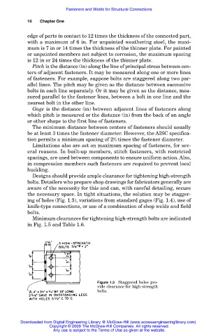
the necessary space. In tight situations, the solution may be stagger-
ing of holes (Fig. 1.3), variations from standard gages (Fig. 1.4), use of
knife-type connections, or use of a combination of shop welds and field
bolts.
Minimum clearances for tightening high-strength bolts are indicated
in Fig. 1.5 and Table 1.6.
Figure 1.3 Staggered holes pro-
vide clearance for high-strength
bolts.
Downloaded from Digital Engineering Library @ McGraw-Hill (www.accessengineeringlibrary.com)
Copyright © 2009 The McGraw-Hill Companies. All rights reserved.
Any use is subject to the Terms of Use as given at the website.