
Page 28 - Handbook of Structural Steel Connection Design and Details
P. 28
Fasteners and Welds for Structural Connections
Fasteners and Welds for Structural Connections 13
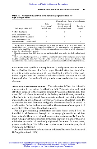
TABLE 1.7 Number of Nut or Bolt Turns from Snug-Tight Condition for
High-Strength Bolts*
Slope of outer faces of bolted parts
Both One face normal
faces normal to bolt axis and Bolt faces
Bolt length (Fig. 1.1) to bolt axis the other sloped † sloped †
Up to 4 diameters 1 ⁄3 1 ⁄2 2 ⁄3
Over 4 diameters but
not more than 8 diameters 1 ⁄2 2 ⁄3 5 ⁄6
Over 5 diameters but
not more than 12 diameters ‡ 2 ⁄3 5 ⁄6 1
*Nut rotation is relative to the bolt regardless of whether the nut or bolt is turned. For bolts
2
installed by ⁄2 turn and less, the tolerance should be ±30°. For bolts installed by ⁄3 turn and more,
1
the tolerance should be ±45°. This table is applicable only to connections in which all material
within the grip of the bolt is steel.
† Slope is not more than 1:20 from the normal to the bolt axis, and a beveled washer is not
used.
‡ No research has been performed by RCSC to establish the turn-of-the-nut procedure for bolt
lengths exceeding 12 diameters. Therefore, the required rotation should be determined by
actual test in a suitable tension-measuring device that simulates conditions of solidly fitted steel.
manufacturer’s specification requirements, and proper pretension can
be verified by the use of a feeler gage. Special attention should be
given to proper installation of flat hardened washers when load-
indicating washers are used with bolts installed in oversize or slotted
holes and when the load-indicating washers are used under the turned
element.
Twist-off-type tension-control bolts. The twist off or TC bolt is a bolt with
an extension to the actual length of the bolt. This extension will twist
off when torqued to the required tension by a special torque gun. The
use of TC bolts have increased for both shop and fieldwork, since they
allow bolts to be tightened from one side, without restraining the ele-
ment on the opposite face. A representative sample of at least three TC
assemblies for each diameter and grade of fastener should be tested in
a calibration device to demonstrate that the device can be torqued to 5
percent greater tension than that required.
For all pretensioning installation methods bolts should first be
installed in all holes and brought to the snug-tight condition. All fas-
teners should then be tightened, progressing systematically from the
most rigid part of the connection to the free edges in a manner that will
minimize relaxation of previously tightened fasteners. In some cases,
proper tensioning of the bolts may require more than a single cycle of
systematic tightening.
An excellent source of information on bolt installation is the Structural
Bolting Handbook (2006).
Downloaded from Digital Engineering Library @ McGraw-Hill (www.accessengineeringlibrary.com)
Copyright © 2009 The McGraw-Hill Companies. All rights reserved.
Any use is subject to the Terms of Use as given at the website.