
Page 32 - Handbook of Structural Steel Connection Design and Details
P. 32
Fasteners and Welds for Structural Connections
Fasteners and Welds for Structural Connections 17
the edges are fully shaped, groove welds made from one side without a
backing bar or made from both sides without back gouging are consid-
ered partial-joint-penetration welds. They are often used for splices in
building columns carrying axial loads only.
Plug and slot welds are used to transmit shear in lap joints and to pre-
vent buckling of lapped parts. In buildings, they also may be used to join
components of built-up members. (Plug or slot welds, however, are not
permitted on A514 steel.) The welds are made, with lapped parts in
contact, by depositing weld metal in circular or slotted holes in one part.
The openings may be partly or completely filled, depending on their
depth. Load capacity of a plug or slot completely welded equals the
product of hole area and available design stress. Unless appearance is
a main consideration, a fillet weld in holes or slots is preferable.
Economy in selection. In selecting a weld, designers should consider not
only the type of joint but also the labor and volume of weld metal
required. While the strength of a fillet weld varies with size, the volume
1
of metal varies with the square of the size. For example, a ⁄2-in fillet weld
1
contains 4 times as much metal per inch of length as a ⁄4-in weld but is
only twice as strong. In general, a smaller but longer fillet weld costs
less than a larger but shorter weld of the same capacity.
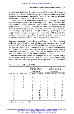
Furthermore, small welds can be deposited in a single pass. Large
welds require multiple passes. They take longer, absorb more weld
metal, and cost more. As a guide in selecting welds, Table 1.8 lists the
TABLE 1.8 Number of Passes for Welds
Single-bevel groove Single-bevel groove
welds (backup weld welds (backup weld
not included) not included)
Weld size,* in Fillet welds 30° bevel 45° bevel 30° open 60° open 90° open
3 1
1 ⁄16
1
1 ⁄4 1 1 1 2 3 3
5 1
1 ⁄16
3 3 2 2 3 4 6
1 ⁄8
7 4
1 ⁄16
1 4 2 2 4 5 7
1 ⁄2
5 6 3 3 4 6 8
1 ⁄8
3 8 4 5 4 7 9
1 ⁄4
7 5 8 5 10 10
1 ⁄8
3 5 11 5 13 22
1 ⁄4
1 7 11 9 15 27
1 ⁄8
1 8 11 12 16 32
1 ⁄4
3 9 15 13 21 36
1 ⁄8
1 9 18 13 25 40
1 ⁄2
3 11 21
1 ⁄4
*Plate thickness for groove welds.
Downloaded from Digital Engineering Library @ McGraw-Hill (www.accessengineeringlibrary.com)
Copyright © 2009 The McGraw-Hill Companies. All rights reserved.
Any use is subject to the Terms of Use as given at the website.