
Page 35 - Handbook of Structural Steel Connection Design and Details
P. 35
Fasteners and Welds for Structural Connections
20 Chapter One
This applies to side and top fillet welds connecting brackets, beam seats,
and similar connections, on the plane about which bending moments are
computed. End returns should be indicated on design and detail drawings.
Filet welds deposited on opposite sides of a common plane of contact
between two parts must be interrupted at a corner common to both
welds. An exception to this requirement must be made when seal weld-
ing parts prior to hot-dipped galvanizing.
If longitudinal fillet welds are used alone in end connections of flat-
bar tension members, the length of each fillet weld should at least equal
the perpendicular distance between the welds.
5
In material ⁄8 in or less thick, the thickness of plug or slot welds
should be the same as the material thickness. In material greater than
5 ⁄8 in thick, the weld thickness should be at least half the material thick-
ness but not less than ⁄8 in.
5
The diameter of the hole for a plug weld should be at least equal to
the depth of the hole plus ⁄16 in, but the diameter should not exceed
5
1
2 ⁄4 times the thickness of the weld.
Thus, the hole diameter in ⁄4-in plate could be a minimum of ⁄4 +
3
3
5 ⁄16 = 1 ⁄16 in. The depth of weld metal would be at least ⁄8 in > ( ⁄2 ×
5
1
1
3
3 ⁄4 = ⁄8 in).
Plug welds may not be spaced closer center-to-center than 4 times the
hole diameter.
The length of the slot for a slot weld should not exceed 10 times the
thickness of the weld. The width of the slot should not be less than the
5
thickness of the part containing it plus ⁄16 in rounded to the next larger
1 ⁄6 in, but the width should not exceed 2 ⁄4 times the weld thickness.
1
Thus, the width of the slot in ⁄4-in plate could be a minimum of ⁄4 +
3
3
1
5
5 ⁄16 = 1 ⁄16 in. The weld metal depth would be at least ⁄8 in > ( ⁄2 × ⁄4 =
1
3
5
3 ⁄8 in). The slot could be up to 10 × ⁄8 = 6 ⁄4 in long.
1
Slot welds may be spaced no closer than 4 times their width in a
direction transverse to the slot length. In the longitudinal direction,
center-to-center spacing should be at least twice the slot length.
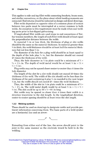
1.3.2 Welding symbols
These should be used on drawings to designate welds and provide per-
tinent information concerning them. The basic parts of a weld symbol
are a horizontal line and an arrow:
Extending from either end of the line, the arrow should point to the
joint in the same manner as the electrode would be held to do the
welding.
Downloaded from Digital Engineering Library @ McGraw-Hill (www.accessengineeringlibrary.com)
Copyright © 2009 The McGraw-Hill Companies. All rights reserved.
Any use is subject to the Terms of Use as given at the website.