
Page 36 - Handbook of Structural Steel Connection Design and Details
P. 36
Fasteners and Welds for Structural Connections
Fasteners and Welds for Structural Connections 21
Welding symbols should clearly convey the intent of the designer. For
this purpose, sections or enlarged details may have to be drawn to show
the symbols, or notes may be added. Notes may be given as part of weld-
ing symbols or separately. When part of a symbol, the note should be
placed inside a tail at the opposite end of the line from the arrow:
The type and length of weld are indicated above or below the line. If
noted below the line, the symbol applies to a weld on the arrow side of
the point, the side to which the arrow points. If noted above the line, the
symbol indicates that the other side, the side opposite the one to which
the arrow points (not the far side of the assembly), is to be welded.
A fillet weld is represented by a right triangle extending above or
below the line to indicate the side on which the weld is to be made. The
vertical leg of the triangle is always on the left.
The preceding symbol indicates that a ⁄4-in fillet weld 6 in long is to be
1
made on the arrow side of the assembly. The following symbol requires
1
a ⁄4-in fillet weld 6 in long on both sides:
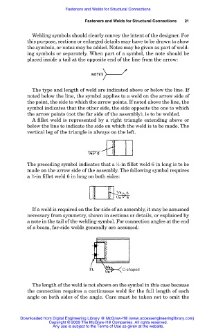
If a weld is required on the far side of an assembly, it may be assumed
necessary from symmetry, shown in sections or details, or explained by
a note in the tail of the welding symbol. For connection angles at the end
of a beam, far-side welds generally are assumed:
C-shaped
The length of the weld is not shown on the symbol in this case because
the connection requires a continuous weld for the full length of each
angle on both sides of the angle. Care must be taken not to omit the
Downloaded from Digital Engineering Library @ McGraw-Hill (www.accessengineeringlibrary.com)
Copyright © 2009 The McGraw-Hill Companies. All rights reserved.
Any use is subject to the Terms of Use as given at the website.