
Page 26 - Handbook of Structural Steel Connection Design and Details
P. 26
Fasteners and Welds for Structural Connections
Fasteners and Welds for Structural Connections 11
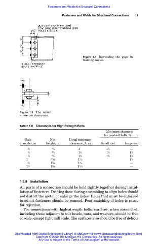
Figure 1.4 Increasing the gage in
framing angles.
Figure 1.5 The usual
minimum clearances.
TABLE 1.6 Clearances for High-Strength Bolts
Minimum clearance
for twist-off bolts, A, in
Bolt Nut Usual minimum
diameter, in height, in clearance, A, in Small tool Large tool
5 39 1 5 —
1 ⁄8 1 ⁄64 1 ⁄8 1 ⁄8
3 47 1 5 7
1 ⁄4 1 ⁄64 1 ⁄4 1 ⁄8 1 ⁄8
7 55 3 5 7
1 ⁄8 1 ⁄64 1 ⁄8 1 ⁄8 1 ⁄8
1 63 7 7
1 ⁄8 ⁄64 1 ⁄16 1 ⁄8
1 7 9 —
1 ⁄8 1 ⁄64 1 ⁄16
1 7 11 —
1 ⁄4 1 ⁄32 1 ⁄16
1.2.8 Installation
All parts of a connection should be held tightly together during instal-
lation of fasteners. Drifting done during assembling to align holes should
not distort the metal or enlarge the holes. Holes that must be enlarged
to admit fasteners should be reamed. Poor matching of holes is cause
for rejection.
For connections with high-strength bolts, surfaces, when assembled,
including those adjacent to bolt heads, nuts, and washers, should be free
of scale, except tight mill scale. The surfaces also should be free of defects
Downloaded from Digital Engineering Library @ McGraw-Hill (www.accessengineeringlibrary.com)
Copyright © 2009 The McGraw-Hill Companies. All rights reserved.
Any use is subject to the Terms of Use as given at the website.