
Page 23 - Handbook of Structural Steel Connection Design and Details
P. 23
Fasteners and Welds for Structural Connections
8 Chapter One
loaded welds. Longitudinal loading is specified since welds become sig-
nificantly less ductile as the loading moves from longitudinal to trans-
verse. This provision assumes that the direction of load is known, which
may not be the case if an eccentric load is present.
In welded alterations to structures, existing rivets and high-strength
bolts tightened to the requirements for slip-critical connections are per-
mitted for carrying stresses resulting from loads present at the time of
alteration. The welding needs to be adequate only to carry the additional
stress.
1.2.6 Standard, oversized, short-slotted,
and long-slotted holes
The AISC specification requires that standard holes for bolts be ⁄16 in
1
larger than the nominal fastener diameter. In computing net area or a
1
tension member, the diameter of the hole should be taken ⁄16 in larger
than the hole diameter.
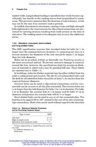
Holes can be punched, drilled, or thermally cut. Punching usually is
the most economical method. To prevent excessive damage to material
around the hole, however, the specifications limit the maximum thick-
ness of material in which holes may be punched full size. These limits
are summarized in Table 1.4.
In buildings, holes for thicker material may be either drilled from the
solid or subpunched and reamed. The die for all subpunched holes and
1
the drill for all subdrilled holes should be at least ⁄16 in smaller than the
nominal fastener diameter.
Oversize holes can be used in slip-critical connections, and the over-
size hole can be in some or all the plies connected. The oversize holes are
5
7
3 ⁄16 in larger than the bolt diameter for bolts ⁄8 to ⁄8 in in diameter. For bolts
1 in in diameter, the oversize hole is ⁄4 in larger and for bolts 1 ⁄8 in in
1
1
diameter and greater, the oversize hole will be ⁄16 in larger.
5
Short-slotted holes can be used in any or all the connected plies. The
load has to be applied 80 to 100° normal to the axis of the slot in bearing-
type connections. Short slots can be used without regard to the direction
TABLE 1.4 Maximum Material Thickness
(in) for Punching Fastener Holes*
Type of steel AISC
1 †
A36 steel d + ⁄8
1 †
High-strength steels d + ⁄8
Quenched and tempered steels 1 ‡
⁄2
*Unless subpunching or subdrilling and reaming
are used.
† d × fastener diameter, in.
‡ A514 steel.
Downloaded from Digital Engineering Library @ McGraw-Hill (www.accessengineeringlibrary.com)
Copyright © 2009 The McGraw-Hill Companies. All rights reserved.
Any use is subject to the Terms of Use as given at the website.