Page 142 - Hardware Implementation of Finite-Field Arithmetic
P. 142

Operations over  Z [ x ]/ f ( x )   125
                                                               p

               c                              ...
                m–1
                         f m–1        f m–2             f 1        f 0
                  c m–2        c m–3             c 0        0
                      mod p        mod p             mod p      mod p
                      multiplier   multiplier       multiplier  multiplier


                     mod p        mod p             mod p     mod p
                    subtractor  a m–1  subtractor  a m–2  subtractor  a 1  subtractor  a 0
               b
                m–1–i                         ...

                         mod p        mod p            mod p      mod p
                        multiplier   multiplier        multiplier  multiplier


                       mod p        mod p            mod p      mod p
                       adder        adder             adder      adder

                       next_c m–1   next_c m–2       next_c  1   next_c 0
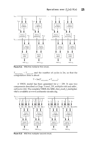
               FIGURE 5.1  MSE-fi rst multiplier fi rst circuit.

               T        + T     , and the number of cycles is 2m, so that the
                mod-p-product  mod-p-sum
               computation time is about
                                T ≈ 2m(T       + T     )
                                        mod-p-product  mod-p-sum
                  A VHDL model has been generated for  p = 239. It uses two
               components described in Chap. 3 (mod_239_multiplier.vhd and adder_
               subtractor.vhd). The complete VHDL file MSE_first_mod_f_multiplier.
               vhd is available at www.arithmetic-circuits.org.

               b                            ...
                m–1–i
                c                           ...
                 m–1
                    c m–2  c m–1  f m–1  a m–1  c m–3  c m–2  f m–2  a m–2  c 0  c 1  f 1  a 1  0 c 0  f 0  a 0
                    10 1 0  1 0  1  0 1 0  1 0  1 0 10  1 0  1 0  1 0  1 0  control


                        mod p       mod p          mod p       mod p
                        multiplier  multiplier    multiplier  multiplier


                       mod p       mod p         mod p        mod p
                      add/subt.   add/subt.      add/subt.   add/subt.

                       next_c     next_c         next_c      next_c
                          m–1         m–2            1           0
               FIGURE 5.2  MSE-fi rst multiplier second circuit.
   137   138   139   140   141   142   143   144   145   146   147