
Page 73 - Hardware Implementation of Finite-Field Arithmetic
P. 73
56 Cha pte r T w o
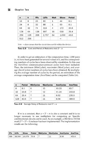
n k FFs LUTs Mult Slices Period
16 8 23 80 1 44 8.1
24 8 32 88 1 50 8.1
64 32 74 319 4 172 20.8
128 64 138 897 16 518 26.4
256 128 268 2,757 64 1,630 43.6
512 256 ∞
Note: ∞ slices means that the circuit does not fit within the device.
k
TABLE 2.5 Cost and Period of Reducers mod 2 − a
In order to get an estimation of the computation time, 1,000 pairs
(x, m) have been generated for several values of k, and the correspond-
ing numbers of cycles have been observed by simulation. In this case
the Start/Done communication-protocol cycles have been included.
Then, the minimum (MinCycles), maximum (MaxCycles), and aver-
age (AverCycles) numbers of cycles have been obtained. By multiply-
ing the average number of cycles by the period, an estimation of the
average computation time (AverTime) can be computed (Table 2.6).
k Period MinCycles MaxCycles AverCycles AverTime
8 8.1 6 15 10.33 83.7
32 20.8 7 12 11.24 233.8
64 26.4 7 11 8.92 235.5
128 43.6 7 11 8.94 389.6
TABLE 2.6 Average Delay of Reducers mod 2 − a
k
If m is a constant, then a = 2 − m is also a constant and it is no
k
longer necessary to use multipliers for computing qa. Specific
combinational circuits can be used. As an example, a 384-bit to 192-bit
64
mod (2 − 2 − 1) reducer has been implemented. The implementation
192
results are the following:
FFs LUTs Slices Period MinCycles MaxCycles AverCycles AverTime
686 38,560 19,978 50.6 7 11 8.96 453.6