
Page 313 - High Power Laser Handbook
P. 313
282 So l i d - S t at e La s e r s Heat-Capacity Lasers 283
10
Parasitic (n = 1.0) Parasitic (n = 1.5) Parasitic (n = 1.62)
8
6 Bond refractive index = 1.0 1.62
ASE multiplier 4 1.5
1.75
2
0
9.6 cm clear aperture
Roughness parameter, ξ = 20
−2
0 0.2 0.4 0.6 0.8 1
Gain coefficient-width product
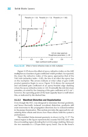
Figure 11.15 Effect of bond refractive index on ASE multiplier.
Figure 11.15 shows the effect of epoxy refractive index on the ASE
multiplier as a function of gain coefficient-width product. As expected,
the closer the refractive index of the epoxy approaches that of the
YAG slab (refractive index ~1.82), the less of an effect the epoxy has
on the multiplier. The arrows indicate at what value of gain-width
product parasitics begin to occur. Figure 11.16 shows the measured
and calculated gain coefficient of an epoxy-bonded edge cladding
where the epoxy refractive index is 1.62. Eventually the slab develops
parasitics, as noted by the clamping of the gain coefficient at 0.11 cm ;
–1
however, the operating point of the heat-capacity laser is well below
this, as indicated by the dashed line.
11.3.3 Wavefront Distortion and Depolarization
Even though the HCL was designed to minimize thermal gradients,
and hence thermally induced wavefront distortion, gradients still
exist transverse to the propagation direction due to nonuniformities
in the pump illumination. This section provides the approach for cal-
culating these effects and shows how these effects limit the system’s
performance.
The modeled finite-element geometry is shown in Fig. 11.17. The
central region in the figure represents the ceramic Nd:YAG slab, with
the surrounding region denoting the Co:GGG edge cladding. Between
the two materials is a 125-mm-thick epoxy bond. Due to the bond’s