
Page 318 - High Power Laser Handbook
P. 318
286 So l i d - S t at e La s e r s Heat-Capacity Lasers 287
Total wavefront@ t = 5.0 s
4
Total wavefront@ t = 5.0 s
15
2
Vertical position (cm) 0 Phase (waves@1 µm) 10
−2 5
0
6
4
−4 2
0 4 6
−2 Vert. pos. (cm) 2
0
−4 −2 0 2 4 −4 −4 −2 Horiz. pos. (cm)
Horizontal position (cm) −6 −6
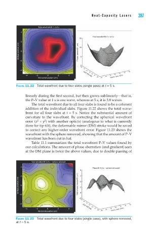
Figure 11.22 Total wavefront due to four slabs (single pass) at t = 5 s.
linearly during the first second, but then grows sublinearly—that is,
the P–V value at 1 s is one wave, whereas at 5 s, it is 3.8 waves.
The total wavefront due to all four slabs is found to be a coherent
addition of the individual slabs. Figure 11.22 shows the total wave-
front for all four slabs at t = 5 s. Notice the substantial amount of
curvature to the wavefront. By correcting the spherical wavefront
2
error (x + y ) with another optic(s) (analogous to what is currently
2
done for tip-tilt), the deformable mirror (DM) stroke would be saved
to correct any higher-order wavefront error. Figure 11.23 shows the
wavefront with the sphere removed, showing that the amount of P–V
wavefront has been cut in haf.
Table 11.1 summarizes the total wavefront P–V values found by
our calculations. The amount of phase aberration (and gradient) seen
at the DM plane is twice the above values, due to double passing of
Total wavefront@ 5.0 s – sphere removed
4
Phase@ 5.0 s – sphere removed
4
2 2
Vertical position (cm) 0 Total phase (waves@1 µm) −2 0
−2 −4
−6
6
4
−4 2
0 4 6
−2 Vert. pos. (cm) 0 2
−4 −2 0 2 4 −4 −2 Horiz. pos. (cm)
−6 −4
Horizontal position (cm) −6
Figure 11.23 Total wavefront due to four slabs (single pass), with sphere removed,
at t = 5 s.