
Page 396 - High Power Laser Handbook
P. 396
The National Ignition Facility Laser 365
Transport
Transport optics Final
Power spatial optics
amplifier filter (TSF) assembly
LM3
Deformable Polarization
mirror (LM1) switch
LM2
Preamp Fiber
Main Cavity spatial Polarizer
amplifier filter (CSF)
Master oscillator
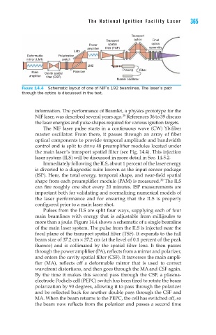
Figure 14.4 Schematic layout of one of NIF’s 192 beamlines. The laser’s path
through the optics is discussed in the text.
information. The performance of Beamlet, a physics prototype for the
35
NIF laser, was described several years ago. References 36 to 39 discuss
the laser energies and pulse shapes required for various ignition targets.
The ΝΙF laser pulse starts in a continuous wave (CW) Yb:fiber
master oscillator. From there, it passes through an array of fiber
optical components to provide temporal amplitude and bandwidth
control and is split to drive 48 preamplifier modules located under
the main laser’s transport spatial filter (see Fig. 14.4). This injection
laser system (ILS) will be discussed in more detail in Sec. 14.5.2.
Immediately following the ILS, about 1 percent of the laser energy
is diverted to a diagnostic suite known as the input sensor package
(ISP). Here, the total energy, temporal shape, and near-field spatial
30
shape from each preamplifier module (PAM) is measured. The ILS
can fire roughly one shot every 20 minutes. ISP measurements are
important both for validating and normalizing numerical models of
the laser performance and for ensuring that the ILS is properly
configured prior to a main laser shot.
Pulses from the ILS are split four ways, supplying each of four
main beamlines with energy that is adjustable from millijoules to
more than a joule. Figure 14.4 shows a schematic of a single beamline
of the main laser system. The pulse from the ILS is injected near the
focal plane of the transport spatial filter (TSF). It expands to the full
beam size of 37.2 cm × 37.2 cm (at the level of 0.1 percent of the peak
fluence) and is collimated by the spatial filter lens. It then passes
through the power amplifier (PA), reflects from a mirror and polarizer,
and enters the cavity spatial filter (CSF). It traverses the main ampli-
fier (MA), reflects off a deformable mirror that is used to correct
wavefront distortions, and then goes through the MA and CSF again.
By the time it makes this second pass through the CSF, a plasma-
electrode Pockels cell (PEPC) switch has been fired to rotate the beam
polarization by 90 degrees, allowing it to pass through the polarizer
and be reflected back for another double pass through the CSF and
MA. When the beam returns to the PEPC, the cell has switched off, so
the beam now reflects from the polarizer and passes a second time