
Page 419 - High Power Laser Handbook
P. 419
The National Ignition Facility Laser 387
SSD, and a 1.8-MJ pulse with a 1.2 mm × 1.3 mm (diameter) focal spot
and 90 GHz of SSD. (In this section, all SSD bandwidths are specified
at 3ω, unless otherwise indicated. To good accuracy, the frequency
converter triples the imposed bandwidth, along with the fundamen-
tal laser frequency.) These fully integrated tests include all three of
NIF’s beam-conditioning techniques simultaneously: phase plates,
SSD, and PS. Table 14.4 shows that the energies, peak powers, focal
spot sizes obtained, and SSD bandwidths for the two candidate
ignition temporal pulse shapes agree with expectations and meet or
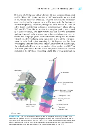
exceed the campaign goals. Polarization smoothing will be accom-
plished on NIF by rotating the polarization in two of the four aper-
tures in each final optics assembly by 90 degrees, and by then
overlapping all four beams at the target. Consistent with this strategy,
the tests described here were conducted with a prototype dKDP 1ω
half-wave plate and a rotated set of frequency conversion crystals
installed in the PDS final optics (Fig. 14.28). The average polarization
1ω
2ω
3ω
Target
Fixed system
3ω diagnostics
3ω Disposable debris
Beam shield
Diagnostic grating and
main debris shield
Wedged focus lens
Frequency conversion
crystals
Integrated optics Vacuum window
module (4 each)
Phase plate
1ω
Beam Polarization rotator
NIF-0406-11894
Figure 14.28 (a) The schematic layout of the final optics assembly on NIF: This
mechanical system mounts to the NIF target chamber and contains the final set of
optics for four NIF beamlines. (b) The suite of optics for one of these beamlines: the
same mechanical, optical, and beam control components that are used in the FOA
at the target chamber are reproduced for a single beamline in the PDS.