
Page 420 - High Power Laser Handbook
P. 420
388 So l i d - S t at e La s e r s The National Ignition Facility Laser 389
(a) (b)
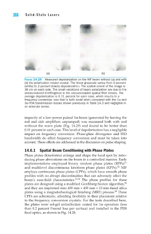
Figure 14.29 Measured depolarization on the NIF beam without (a) and with
(b) the polarization rotator crystal. The linear grayscale varies from 0 percent
(white) to 2 percent (black) depolarization. The spatial extent of the image is
38 cm on each side. The small variations of beam polarization are due to the
stress-induced birefringence in the vacuum-loaded spatial filter lenses. The
average depolarization is 0.11 percent for each case, which results in a
frequency conversion loss that is both small when compared with the 1ω and
3ω FOA transmission losses shown previously in Table 14.3 and negligible in
an absolute sense.
impurity of a low-power pulsed 1ω beam (generated by leaving the
rod and slab amplifiers unpumped) was measured both with and
without the wave plate (Fig. 14.29) and found to be better than
0.11 percent in each case. This level of depolarization has a negligible
impact on frequency conversion. Phase-plate divergence and SSD
bandwidth do affect frequency conversion and must be taken into
account. These effects are addressed in the discussion on pulse shaping.
14.6.1 Spatial Beam Conditioning with Phase Plates
Phase plates (kinoforms) enlarge and shape the focal spot by intro-
ducing phase aberrations on the beam in a controlled manner. Early
51
implementations employed binary random phase plates (RPPs)
52
and multilevel discontinuous kinoform phase plates (KPPs). NIF
employs continuous phase plates (CPPs), which have smooth phase
profiles with no abrupt discontinuities that can adversely affect the
beam’s near-field characteristics. 53,54 The phase profiles for these
53
plates are designed using a modified Gerchberg-Saxton algorithm,
and they are imprinted onto 430 mm × 430 mm × 10 mm fused silica
plates using a magnetorheological finishing (MRF) process. These
55
CPPs are achromatic, affording flexibility in their placement relative
to the frequency conversion crystals. For the tests described here,
the plates were sol-gel antireflection coated for 1ω operation (less
than 0.2 percent Fresnel loss per surface) and installed in the PDS
final optics, as shown in Fig. 14.28.