
Page 205 - High Temperature Solid Oxide Fuel Cells Fundamentals, Design and Applications
P. 205
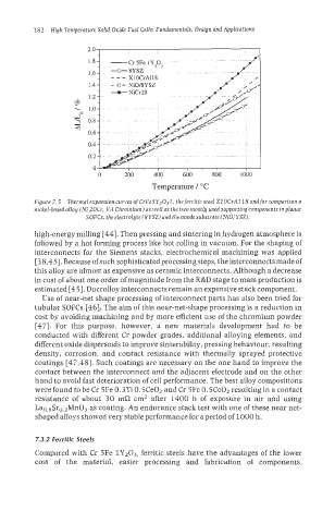
182  High Temperature Solid Oxide Fuel Cells: Fundamentals, Design and Applications


                              -o-   NiCr20


                           0     200     400     600    800     1000
                                         Temperature / "C
          Figure 7.5  Thermal expansion curves of CrFe5Yz037, theferritic steel XI OCrAll8 andfor comparison a
          nickel-based alloy (Ni 20Cr, VA Chromium) as well as the two mostly used supporting components in planar
                       SOFCs, the electrolyte (SYSZ) and the anode substrate (NiOJYSZ).
          high-energy milling [44]. Then pressing and sintering in hydrogen atmosphere is
          followed by a hot forming process like hot rolling in vacuum. For the shaping of
          interconnects for the Siemens stacks, electrochemical machining was  applied
          [3 8,451. Because  of such sophisticated processing steps, the interconnects made of
          this alloy are almost as expensive as ceramic interconnects. Although a decrease
          in cost of about one order of magnitude from the R&D stage to mass production is
          estimated [45], DucrolIoy interconnects remain an expensive stack component.
            Use of near-net shape processing of interconnect parts has also been tried for
          tubuIar SOFCs [46]. The aim of this near-net-shape processing is a reduction in
          cost by avoiding machining and by more efficient use of  the chromium powder
          [47].  For  this  purpose,  however,  a  new  materials  development  had  to  be
          conducted with different Cr  powder  grades, additional  alloying elements, and
          different oxide dispersoids to improve sinterability, pressing behaviour, resulting
          density, corrosion, and  contact resistance  with  thermally  sprayed protective
          coatings [47,48]. Such coatings are necessary on the one hand to improve the
          contact between the interconnect and the adjacent electrode and on the other
          hand to avoid fast deterioration of cell performance. The best alloy compositions
          were found to be Cr 5Fe 0.3Ti 0.5Ce02 and Cr 5Fe 0.5Ce02 resulting in a contact
          resistance  of  about  30 mC2  cm2 after  1400 h  of  exposure  in  air  and  using
          Lao.8Sro,2Mn03 as coating. An endurance stack test with one of these near net-
          shaped alloys showed very stable performance for a period of 1000 h.


          7.3.2 Ferritic Steels
          Compared with Cr  5Fe 1Y203, ferritic steels have the advantages of  the lower
          cost  of  the  material,  easier  processing  and  fabrication  of  components,