
Page 307 - High Temperature Solid Oxide Fuel Cells Fundamentals, Design and Applications
P. 307
Testing of Electrodes. Cells and Short Stacks 283
-0.04 1
-0.03 -
1Hz o
A lOHz
G. -0.02 -
0) 1OOHz A
m
.E -0.01 -
t4 Rs
0 -'
0.01 J
0 0.02 0.04 0.06 0.08
Z-reai (Q)
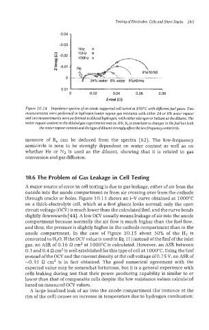
Figure 10.14 Impedance spectra of an anode-supported cell tested at 850°C with different fuel gases. Two
measurements were performed in hgdrogenlwater vapour gas mixtures with either 24 or 6% water vapour
and two measurements wereperformed indiluted hydrogen, witheither nitrogen or helium as the diluent. The
water vapour confent in thedilutedgas experiments wasca. 6%. R, isinvariant tochanges in thefuel but both
the water vapour content and the type of diluent strongly affect the low frequency semicircle.
measure of R, can be deduced from the spectra [62]. The low-frequency
semicircle is seen to be strongly dependent on water content as well as on
whether He or N2 is used as the diluent, showing that it is related to gas
conversion and gas diffusion.
1Q.6 The Problem of Gas leakage in Cell Testing
A major source of error in cell testing is due to gas leakage, either of air from the
outside into the anode compartment or from air crossing over from the cathode
through cracks or holes. Figure 10.15 shows an i-V curve obtained at 1000°C
on a thick-electrolyte cell, which at a first glance looks normal: only the open
circuit voltage (OCV) is much lower than the calculated Emf, and the curve bends
slightly downwards [44]. A low OCV usually means leakage of air into the anode
compartment because normally the air flow is much higher than the fuel flow,
and thus, the pressure is slightly higher in the cathode compartment than in the
anode compartment. In the case of Figure 10.15 about 50% of the H2 is
converted to H20. If the OCV value is used in Eq. (1) instead of the Emf of the inlet
gas, an ASR of 0.16 s1 cm2 at 1000°C is calculated. However, an ASR between
0.3 and 0.4 C2 cm2 is well established for this type ofcell at 1000°C. Using the Emf
instead of the OCV and the current density at the cell voltage of 0.75 V. an ASR of
-0.35 s1 cm2 is in fact obtained. The good numerical agreement with the
expected value may be somewhat fortuitous, but it is a general experience with
cells leaking during test that their power producing capability is similar to or
lower than that of comparable cells despite the low resistance values calculated
based on measured OCV values.
A large localised leak of air into the anode compartment (for instance at the
rim of the cell) causes an increase in temperature due to hydrogen combustion;