
Page 308 - High Temperature Solid Oxide Fuel Cells Fundamentals, Design and Applications
P. 308
284 High Temperature Solid Oxide Fuel Cells: Fundamentals, Design and Applications
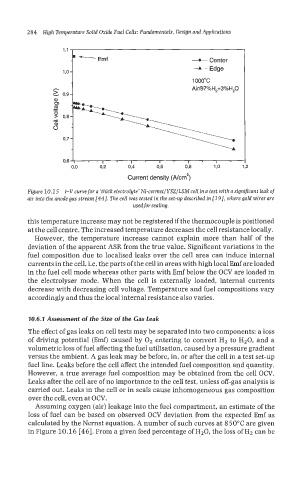
4- Center
-A- Edge
1 ooooc
Air/97%H2+3%H20
h
L 0,9
I I I I I
0,o 02 0,4 0,6 03 1,o 12
Current density (Ncm')
Figure 10.15 i-Vcurwe for a 'thick electrolyte' Ni-cermet/YSZ/LSM cell in a test with a sign$cant leak of
air into the anode gas stream [44]. The cell was tested in the set-up described in 1191, where gold wires are
usedfor sealing.
this temperature increase may not be registered if the thermocouple is positioned
at the cell centre. The increased temperature decreases the cell resistance locally.
However, the temperature increase cannot explain more than half of the
deviation of the apparent ASR from the true value. Significant variations in the
fuel composition due to localised leaks over the cell area can induce internal
currents in the cell, i.e. the parts of the cell in areas with high local Emf are loaded
in the fuel cell mode whereas other parts with Emf below the OCV are loaded in
the electrolyser mode. When the cell is externally loaded, internal currents
decrease with decreasing cell voltage. Temperature and fuel compositions vary
accordingly and thus the local internal resistance also varies.
70.6.7 Assessment of the Size of the Gas Leak
The effect of gas leaks on cell tests may be separated into two components: a loss
of driving potential (Emf) caused by O2 entering to convert H2 to H20, and a
volumetric loss of fuel affecting the fuel utilisation, caused by a pressure gradient
versus the ambient. A gas leak may be before, in, or after the cell in a test set-up
fuel line. Leaks before the cell affect the intended fuel composition and quantity,
However, a true average fuel composition may be obtained from the cell OCV.
Leaks after the cell are of no importance to the cell test, unless off-gas analysis is
carried out. Leaks in the cell or in seals cause inhomogeneous gas composition
over the cell, even at OCV.
Assuming oxygen (air) leakage into the fuel compartment, an estimate of the
loss of fuel can be based on observed OCV deviation from the expected Emf as
calculated by the Nernst equation. A number of such curves at 8 50°C are given
in Figure 10.16 [46]. From a given feed percentage of H20, the loss of H2 can be