
Page 82 - Hybrid-Renewable Energy Systems in Microgrids
P. 82
66 Hybrid-Renewable Energy Systems in Microgrids
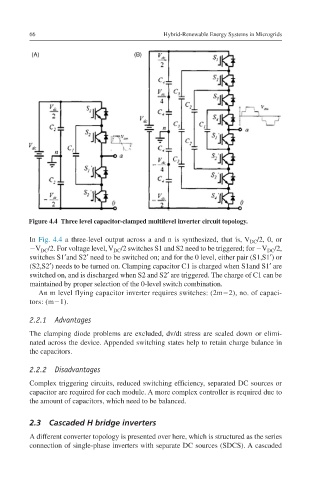
Figure 4.4 Three level capacitor-clamped multilevel inverter circuit topology.
In Fig. 4.4 a three-level output across a and n is synthesized, that is, V DC /2, 0, or
−V DC /2. For voltage level, V DC /2 switches S1 and S2 need to be triggered; for −V DC /2,
switches S1′and S2′ need to be switched on; and for the 0 level, either pair (S1,S1′) or
(S2,S2′) needs to be turned on. Clamping capacitor C1 is charged when S1and S1′ are
switched on, and is discharged when S2 and S2′ are triggered. The charge of C1 can be
maintained by proper selection of the 0-level switch combination.
An m level flying capacitor inverter requires switches: (2m−2), no. of capaci-
tors: (m−1).
2.2.1 Advantages
The clamping diode problems are excluded, dv/dt stress are scaled down or elimi-
nated across the device. Appended switching states help to retain charge balance in
the capacitors.
2.2.2 Disadvantages
Complex triggering circuits, reduced switching efficiency, separated DC sources or
capacitor are required for each module. A more complex controller is required due to
the amount of capacitors, which need to be balanced.
2.3 Cascaded H bridge inverters
A different converter topology is presented over here, which is structured as the series
connection of single-phase inverters with separate DC sources (SDCS). A cascaded