
Page 78 - Hybrid-Renewable Energy Systems in Microgrids
P. 78
62 Hybrid-Renewable Energy Systems in Microgrids
One of the major drawbacks of the topology is that larger number of power semi-
conductor switches, which adds on to the complexity and cost of the system as each
switch has a related gate driver circuit. Great attention is being given on the studies to
reduce the number of power electronic switches thereby reducing the complexity of
the circuit and the requirements of gate triggering circuits.
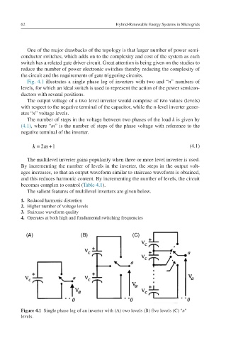
Fig. 4.1 illustrates a single phase leg of inverters with two and “n” numbers of
levels, for which an ideal switch is used to represent the action of the power semicon-
ductors with several positions.
The output voltage of a two level inverter would comprise of two values (levels)
with respect to the negative terminal of the capacitor, while the n-level inverter gener-
ates “n” voltage levels.
The number of steps in the voltage between two phases of the load k is given by
(4.1), where “m” is the number of steps of the phase voltage with reference to the
negative terminal of the inverter.
2
+
k=2m+1 k = m 1 (4.1)
The multilevel inverter gains popularity when three or more level inverter is used.
By incrementing the number of levels in the inverter, the steps in the output volt-
ages increases, so that an output waveform similar to staircase waveform is obtained,
and this reduces harmonic content. By incrementing the number of levels, the circuit
becomes complex to control (Table 4.1).
The salient features of multilevel inverters are given below.
1. Reduced harmonic distortion
2. Higher number of voltage levels
3. Staircase waveform quality
4. Operates at both high and fundamental switching frequencies
Figure 4.1 Single phase leg of an inverter with (A) two levels (B) five levels (C) ''n''
levels.