
Page 81 - Hybrid-Renewable Energy Systems in Microgrids
P. 81
Multilevel inverters: an enabling technology 65
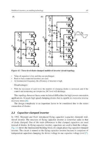
Figure 4.3 Three-level diode-clamped multilevel inverter circuit topology.
• Value of capacitor is low and they are precharged.
• Back to back connected inverters are used.
• At fundamental frequency, the efficiency of inverter is high.
Disadvantages:
• With the increment of each level, the number of clamping diodes is increased, and if the
control and monitoring are not precise, DC level will discharge.
This topology however faces some technical difficulties for high power conversion
applications. It needs high speed clamping diodes that is capable to overcome reverse
recovery stress [6].
The design complexity is an important factor to be considered due to the series
connection of diodes.
2.2 Capacitor-clamped inverter
In 1992, Meynard and Foch introduced flying capacitor (capacitor clamped) mul-
tilevel inverter. The structure of flying capacitor inverter is somewhat same to that
of diode clamped. One of the main differences is that clamped capacitors are used
instead of diodes. In flying capacitor inverter, capacitors are used to limit the voltage.
Fig. 4.4 shows the fundamental building block of a single phase-leg capacitor-clamped
inverter. The circuit is named as the flying capacitor inverter because it comprises of
independent capacitors clamping the device voltage to one capacitor voltage level [7].