
Page 80 - Hybrid-Renewable Energy Systems in Microgrids
P. 80
64 Hybrid-Renewable Energy Systems in Microgrids
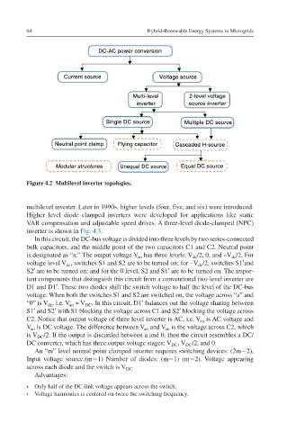
Figure 4.2 Multilevel inverter topologies.
multilevel inverter. Later in 1990s, higher levels (four, five, and six) were introduced.
Higher level diode clamped inverters were developed for applications like static
VAR compensation and adjustable speed drives. A three-level diode-clamped (NPC)
inverter is shown in Fig. 4.3.
In this circuit, the DC-bus voltage is divided into three levels by two series-connected
bulk capacitors, and the middle point of the two capacitors C1 and C2. Neutral point
is designated as “n.” The output voltage V has three levels: V /2, 0, and –V /2. For
an
dc
dc
voltage level V , switches S1 and S2 are to be turned on; for –V /2, switches S1′and
dc
dc
S2′ are to be turned on; and for the 0 level, S2 and S1′ are to be turned on. The impor-
tant components that distinguish this circuit from a conventional two-level inverter are
D1 and D1′. These two diodes shift the switch voltage to half the level of the DC-bus
voltage. When both the switches S1 and S2 are switched on, the voltage across “a” and
“0” is V , i.e. V = V . In this circuit, D1′ balances out the voltage sharing between
ao
dc
DC
S1′ and S2′ with S1 blocking the voltage across C1 and S2′ blocking the voltage across
C2. Notice that output voltage of three level inverter is AC, i.e. V is AC voltage and
an
V is DC voltage. The difference between V and V is the voltage across C2, which
ao
an
ao
is V /2. If the output is discarded between a and 0, then the circuit resembles a DC/
DC
DC converter, which has three output voltage stages: V , V /2, and 0.
DC
DC
An “m” level neutral point clamped inverter requires switching devices: (2m−2),
Input voltage source:(m−1) Number of diodes: (m−1) (m−2). Voltage appearing
across each diode and the switch is V DC.
Advantages:
• Only half of the DC-link voltage appears across the switch.
• Voltage harmonics is centered on twice the switching frequency.