
Page 406 - Hydrocarbon Exploration and Production Second Edition
P. 406
Managing the Producing Field 393
tubing size
P i
2 7/8"
Flowing bottom hole pressure (psig) P 2 5 1/2"
3 1/2"
IPR 1
unstable
flow
IPR 2
stable
Liquid flow rate (stb/d) flow
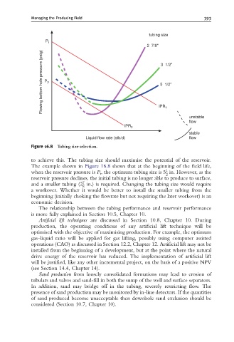
Figure 16.8 Tubing size selection.
to achieve this. The tubing size should maximise the potential of the reservoir.
The example shown in Figure 16.8 shows that at the beginning of the field life,
1
when the reservoir pressure is P i , the optimum tubing size is 5 in. However, as the
2
reservoir pressure declines, the initial tubing is no longer able to produce to surface,
7
and a smaller tubing (2 in.) is required. Changing the tubing size would require
8
a workover. Whether it would be better to install the smaller tubing from the
beginning (initially choking the flowrate but not requiring the later workover) is an
economic decision.
The relationship between the tubing performance and reservoir performance
is more fully explained in Section 10.5, Chapter 10.
Artificial lift techniques are discussed in Section 10.8, Chapter 10. During
production, the operating conditions of any artificial lift technique will be
optimised with the objective of maximising production. For example, the optimum
gas–liquid ratio will be applied for gas lifting, possibly using computer assisted
operations (CAO) as discussed in Section 12.2, Chapter 12. Artificial lift may not be
installed from the beginning of a development, but at the point where the natural
drive energy of the reservoir has reduced. The implementation of artificial lift
will be justified, like any other incremental project, on the basis of a positive NPV
(see Section 14.4, Chapter 14).
Sand production from loosely consolidated formations may lead to erosion of
tubulars and valves and sand-fill in both the sump of the well and surface separators.
In addition, sand may bridge off in the tubing, severely restricting flow. The
presence of sand production may be monitored by in-line detectors. If the quantities
of sand produced become unacceptable then downhole sand exclusion should be
considered (Section 10.7, Chapter 10).