
Page 181 - Hydrogeology Principles and Practice
P. 181
HYDC05 12/5/05 5:35 PM Page 164
164 Chapter Five
3 Measure water depth, d, and current meter count
rate at a depth of 0.4 d from the bed of the river, if
d ≤ 0.75 m, or 0.2 d and 0.8 d if d ≥ 0.75 m, at 20 equal
intervals across the section. Provided that the veloc-
ity profile is logarithmic, the point velocity at 0.4 d
or (0.2 d + 0.8 d)/2 represents the mean velocity
for the vertical. When taking velocity readings it is
necessary to stand 0.5 m downstream and to one side
of the meter, to hold the wading rod vertically, and
to ensure that the meter is aligned perpendicular to
the section.
4 Convert count rate values to velocities using a
calibration equation.
5 Assuming that the average velocity at a vertical is
representative of the area bounded by the mid-points
between adjacent verticals, calculate the discharge
(velocity × area) for each segment. The discharges
for each segment are then summed to obtain the total
discharge of the section (Fig. 5.20).
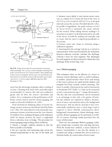
Fig. 5.19 Design of two types of current meter for measuring
5.6.2 Dilution gauging
stream discharge. The cup type (a) has an impeller consisting of six
small cups which rotate on a horizontal wheel. The propeller type
(b) has a rotor as an impeller. In both types, the rate of rotation of This technique relies on the dilution of a tracer to
the impeller is recorded by an electrically operated counter and is measure stream discharge and is a useful technique
converted to a velocity using a calibration equation. After in smaller, upland streams where flows and mixing
Brassington (1998).
of the tracer solution are rapid and the shallow and
irregular bed form exclude current metering. The
meter has the advantage of giving a direct reading of tracer is usually a fluorescent dye such as fluorescein
velocity. Cleaning with clean water and mild soap is or rhodamine WT (Table 5.11) that can be measured
−1
recommended to remove dirt and non-conductive at trace concentrations (µgL ) using a fluorometer.
grease and oil from the sensor’s electrodes and The fact that low concentrations can be measured
surface. For a comparison of the performance of dif- is an advantage in that only a few grams of harm-
ferent current meters used for stream gauging, the less dye solution are required to obtain a measure-
reader is referred to Fulford et al. (1993). ment of tracer concentration above the background
Field methods for obtaining values of stream dis- fluorescence. Salt can also be used but is less envir-
charge across a section are described in detail by Rantz onmentally satisfactory since a much larger mass is
et al. (1982). The main objective is the systematic mea- required to detect chloride concentrations above
surement of point velocities across the river channel. background concentrations. Steam discharge meas-
For shallow rivers, wading techniques can be employed, ured by dilution gauging can be estimated to within
while for deeper sections the meter is suspended 2% of current metering results provided that the
from a cableway, boat or bridge. The procedure for tracer is fully mixed.
stream gauging using wading rods is as follows: There are two principal dilution gauging techni-
1 Choose a straight, uniform channel so that the ques: steady-state (constant rate) and slug injection.
flow is parallel to the banks. With the steady-state method, a tracer solution of
2 Set up a tag line and measuring tape across the known concentration is run into the stream at a
channel perpendicular to the line of the bank and constant rate using a constant flow device such as a
secure. Mariotte bottle. By conservation of tracer mass: