
Page 184 - Hydrogeology Principles and Practice
P. 184
HYDC05 12/5/05 5:35 PM Page 167
Groundwater investigation techniques 167
Table 5.7 Table of typical values of Manning’s n for application in where f is the Darcy–Weisbach friction factor, g is
the estimation of stream discharge. After Wilson (1990). gravitational acceleration and v, R and S are as
defined for equation 5.18. The friction factor, or flow
Type of channel n
resistance, is dependent on the flow geometry, the
Smooth timber 0.011 roughness height of the stream bed and the cross-
Cement-asbestos pipes, welded steel 0.012 sectional variation in roughness heights.
Concrete-lined (high-quality formwork) 0.013
Brickwork well laid and flush jointed 0.014
Concrete and cast iron pipes 0.015
Rolled earth: brickwork in poor condition 0.018 5.6.5 Weirs and flumes
Rough-dressed-stone paved, without sharp bends 0.021
Natural stream channel, flowing smoothly in clean 0.030 A gauging station is a site on a river which has been
conditions selected, equipped and operated to provide the basic
Standard natural stream or river in stable condition 0.035 data from which systematic records of water level
River with shallows and meanders and noticeable 0.045
aquatic growth and stream discharge may be derived. Essentially, a
River or stream with rocks and stones, shallow and weedy 0.060 gauging station consists of an artificial river cross-
Slow-flowing meandering river with pools, slight rapids, 0.100 section (a weir) where a continuous record of stage
very weedy and overgrown (water level upstream of the weir crest) can be obtained
and where a relation between the stage and dis-
charge, known as the rating curve, can be determined.
that the roughness coefficient for the stretch of
channel can be determined. This estimation method
is particularly useful for reconnaissance surveys and
for estimating flood flows after the peak discharge
has subsided. The procedure is as follows:
1 Estimate the roughness coefficient (Manning’s n)
for the channel from a set of photographs of similar
channels with known values of n or from a table of
values (Table 5.7).
2 Measure the slope, S, of the water surface over a
distance of approximately 200 m.
3 Survey the cross-section of the channel at a rep-
resentative site to obtain the hydraulic radius, R,
equal to the cross-sectional area of flow divided by
the wetted perimeter.
4 Calculate the average velocity, v, in units of m s −1
using the Manning formula:
/ 23 1
=
v RS /2 eq. 5.18
n
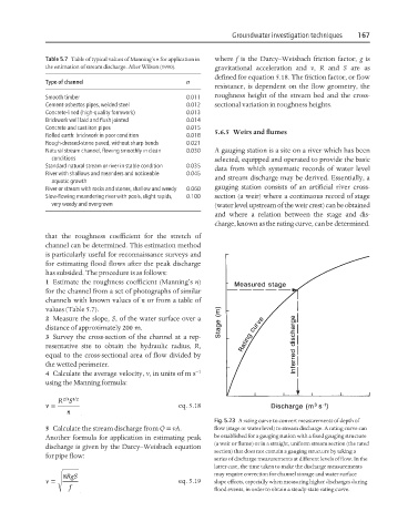
Fig. 5.23 A rating curve to convert measurements of depth of
5 Calculate the stream discharge from Q = vA. flow (stage or water level) to stream discharge. A rating curve can
Another formula for application in estimating peak be established for a gauging station with a fixed gauging structure
(a weir or flume) or in a straight, uniform stream section (the rated
discharge is given by the Darcy–Weisbach equation
section) that does not contain a gauging structure by taking a
for pipe flow:
series of discharge measurements at different levels of flow. In the
latter case, the time taken to make the discharge measurements
=
v 8 RgS eq. 5.19 may require correction for channel storage and water surface
slope effects, especially when measuring higher discharges during
f
flood events, in order to obtain a steady-state rating curve.