
Page 185 - Hydrogeology Principles and Practice
P. 185
HYDC05 12/5/05 5:35 PM Page 168
168 Chapter Five
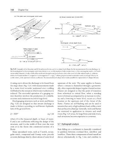
Fig. 5.24 Examples of (a) thin plate and (b) broad crested weirs, and (c) a critical depth flume for the measurement of stream discharge. In
the formula given for the rectangular notch weir shown in (a), n is the number of side constrictions (= 2 for a rectangular notch; = 0 if notch
across whole channel), b is the width of the notch and H is upstream head of water above the crest. In (b) the critical depth, d , is shown
c
where the Froude number, F, is equal to 1 in the equation F = v/(gd ) where g is gravitational acceleration and v is average velocity. In
1 / 2
c
(c) the term C is the approach velocity coefficient. The introduction of a shape factor is also possible for trapezoidal or U-shaped throats.
v
A rating curve allows the discharge to be found from upstream of the weir. The same applies to flumes,
the stage alone (Fig. 5.23) with measurements made where a stream is channelled through a geometric-
by a water level recorder positioned over a stilling ally, often trapezoidal-shaped regular channel section.
well linked to the stream in which water turbulence is Flumes are designed so that the point of transition
reduced. The successful operation of a gauging sta- from subcritical to critical flow, when a standing
tion therefore involves the production of a reliable, wave is formed accompanied by an increase in veloc-
accurate and continuous record of stage level. ity and a lowering in water level, occurs at a fixed
Fixed gauging structures such as weirs and flumes location at the upstream end of the throat of the
(Fig. 5.24) are designed so that stream discharge is flume. Flumes are self-flushing and can be used in
made to behave according to well-known hydraulic streams that carry a high sediment load, unlike a weir
laws of the general form: that can become silted up. Generally, weirs and flumes
are restricted in application to streams and small
Q = KbH a eq. 5.20 rivers (Fig. 5.25) since, for large flows and wide rivers,
such structures become expensive to construct.
where H is the measured depth, or head, of water,
K and a are coefficients reflecting the design of the
structure, and b is the width of flow over the weir 5.7 Hydrograph analysis
crest or in the throat (the constricted section) of a
flume. Rain falling on a catchment is classically considered
Many specialized weirs, such as V-notch, rectan- to partition between overland flow, interflow and
gular notch, compound and Crump weirs, provide baseflow. These three components of total runoff are
accurate discharge data by observations of water level shown schematically in Fig. 5.26a and combine to